Content
| About this module | Installation: electrical |
| Technical data | Installation: commissioning |
| Included items | Troubleshooting |
| Installation: general guidelines | Replacement parts |
| Installation: mechanical |
About this module
The Mixergy PV switch is an intermediary relay device which allows external 3rd party PV diverters to be integrated with the Mixergy cylinder and share use of the primary immersion.
Under idle conditions, control of the immersion is given to the PV diverter. Whenever the Mixergy controller calls for heat through the immersion via boost or a scheduled heating event, control of the immersion is switched away from the PV diverter and given to the Mixergy controller.
Technical data
| Supported (input) diverter(s) | 1 |
| Supported (output) immersion(s) | 1 |
| Supported immersion rating | 230-240 V~ 2.7-3.0 kW |
| Supported immersion specification | EN 60335-2-73 |
| Max. idle consumption (12V) | 250 mW |
| Max. active consumption (12V) | 1500 mW |
Included items
- MAS0086-01 PV ready switch box complete
- MEL0049 2m pump cable extension
- 2x MME0077 Screw No 8 x 13mm Self Drilling
- 2x MME0152 Plastic spacer
- Installation guide
Installation: General guidelines
 ENSURE ALL ELECTRICAL SUPPLIES ARE SWITCHED OFF BEFORE MAKING ANY CONNECTION TO THE UNIT. ELECTRICAL INSTALLATION MUST BE CARRIED OUT BY A COMPETENT ELECTRICIAN AND BE IN ACCORDANCE WITH THE LATEST I.E.E.
REGULATIONS.
Ensure that all mains cabling used have a minimum CSA of 1.5 mm2 with a minimum temperature rating of 90C (H05V2V2-F).
Avoid fitting the PV switch or making electrical junctions directly underneath water pipework.
The PV switch can be fixed to the outer wrapper of the cylinder using the two self-drilling screws or to an adjacent wall using the provided plastic spacers. In the case of a wall mount, the immersion cable will need to be extended. Ensure that the junction used to perform this extension has a minimum IP41 rating and is appropriately rated to handle 240V~ 13A continuous.
Installation: mechanical
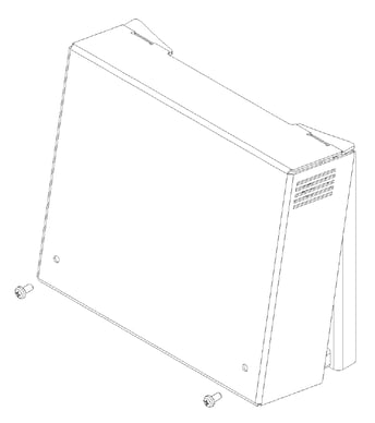
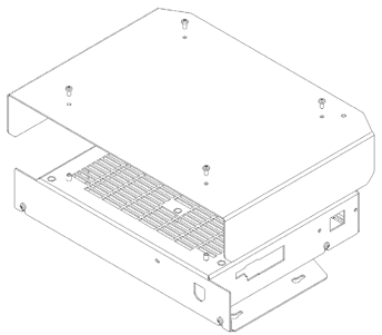
1. Remove the front cover of the PV switch.
2. Mount the PV switch either to the side wall of the cylinder (using the included self-drilling screws) or to a nearby wall (using the included plastic spacers).
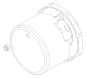
3. Remove the cover/cap on the primary immersion heater. Disconnect the Mixergy controller’s immersion supply cable from the immersion’s terminals.
Installation: electrical
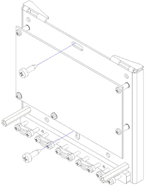
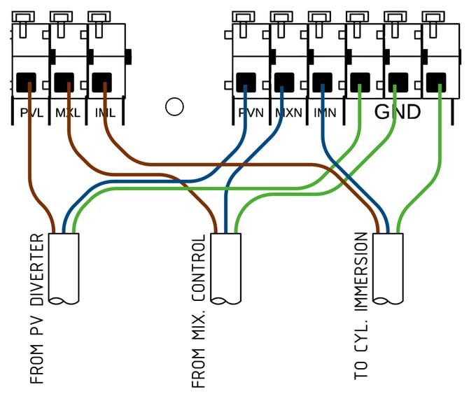
4. Disconnect the existing wiring to the immersion heater. Connect these wires to terminals MXL(L), MXN(N), GND(E) on the PV switch. This cable can be extended using 1.5mm2 CSA 3-core H05V2V2-F flex if required.
5. Connect the third party PV diverter output to terminals PVL(L), PVN(N), GND(E) on the PV switch using 1.5mm2 CSA 3-core H05V2V2-F flex.
6. Connect the immersion heater to PV switch terminals IML(L), IMN(N), GND(E)using 1.5mm2 CSA 3-core H05V2V2-F flex.
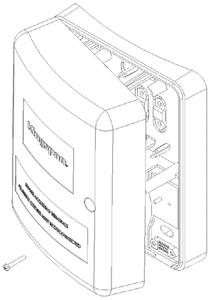
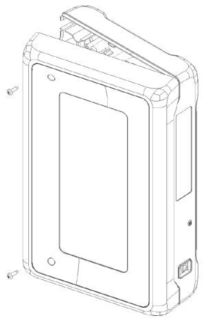
7. Remove the Mixergy cylinder controller's top cover by unscrewing the screws as shown opposite and pulling the cover away.
8. Unplug the pump cable (white 3-pole connector at the bottom right of the controller circuit board) from the cylinder controller. Connect one end of the supplied pump extension cable in it's place. Connect the other end of the pump extension cable to one of the two PUMP connectors on the PV switch.
9. Connect the cable from the Mixergy pump to the remaining PUMP connector on the PV switch.
10. Adjust the immersion thermostat to approx. 65 C. For thermostats without discrete temperature steps, move the dial to the 3/4 of max position. Note that this may need to be adjusted after the system has been tested.
11. Replace immersion cover, PV switch cover and cylinder controller cover.
Installation: commissioning
1. Restore power to the external diverter and Mixergy controller
2. Cancel and schedule heating events/boosts from the Mixergy controller (if active).
3. Set the PV diverter to bypass/boost and check that the immersion is heating via the diverter.
4. Set the Mixergy controller heat source to electric and boost using the gauge; observe that the bypass/boost function of the diverter is switched off and the cylinder continues to heat via. the Mixergy controller supply.
5. Set the exchanger circulator pump speed to setting II for heat pumps, I for solar thermal.
Troubleshooting
Diverter not working correctly
If the diverter is unable to supply heat to the cylinder, perform the following checks:
- Check that the cylinder is not entirely full of hot water (i.e. 100% charged). If the cylinder is full of hot water, drain the cylinder down 20-30% and repeat the commissioning steps.
- Check that the cylinder immersion thermostat is adjusted to approximately 65 C.
- Check that the diverter is set up correctly according to the manufacturer's instructions.
RCD tripping
If an RCD is tripping when the cylinder is switched on, double-check all mains wiring to the PV switch, diverter and cylinder immersion.
Electrical fault
If an electrical fault of the controller is suspected or the electrical system does not operate as expected, please contact Mixergy directly.
Replacement parts
| Part description | Part Number |
| PV Switch PCBA | MAS0085 |
| PV Switch enclosure lid | MME0144 |
| Pump cable extension | MAS0090 |