MDC0031: Mixergy iHP X Installation and Servicing Manual
For the R290 stainless steel Integrated Heat Pump (iHP X) cylinders. This guide is version MDC0031-05.
Download the current iHP X Installation and Servicing Manual
Manual Contents
- Technical data
- What's in the box?
- Installer notes
- Schematic
- Hydraulic schematic
- Installation: General guidelines
- Installation: Head pump head unit
- Building regulation G3 discharge requirements
- Installation: Electrical
- Installation: Connectivity
- Current reader kit installation (option)
- Controller connector positions
- Commissioning
- Draining the cylinder
- Replacement parts
- Servicing and maintenance
Technical data
| Max. supply pressure to pressure-reducing valve | 10 bar |
| Operating pressure | 3 bar |
| Expansion vessel charge pressure | 3 bar |
| Expansion relief valve setting | 6 bar |
| P&T relief valve setting (pressure) | 7 bar |
| P&T relief valve setting (temperature) | 90 °C |
| Thermostat safety cut-out temperature | 80 °C |
| Adjustable temperature range (head unit only) | 45-65 °C (59 °C) |
| Heat pump consumption (cont.) | 230-240 V~ 550W |
| Heat pump rating | 1.5kW |
| Refrigerant (Charge) | R290 (150g) |
What's the box?
- iHP water cylinder
- iHP heat pump unit
- Pre plumb flexi-hoses
- Spare blanking cap for condensate tray
- Combination (monobloc) valve
- Mixergy Gauge
- Tundish
- Expansion vessel including mounting bracket and 3/4” x 22mm
adapters - Powerline to Ethernet adapter
- Ethernet cable (1m)
- Mixergy iHP User Guide
- Installation and Servicing Instructions (this document)
Optional components
- Single phase energy measurement kit (MAS0071)
Note: Ducting and insulation are not included
Installer Notes
Installers must be appropriately qualified to G3 standard to install this cylinder.
All models are factory fitted / supplied with immersion heaters that have built-in thermal cut-outs. Immersion heaters without thermal cut-outs must not be fitted.
All unvented installations must be fitted with a pressure reducing valve (supplied) and P&T relief valve (fitted). These must not be removed or used for any other purposes than what they are designed for.
The unit is supplied in two parts (the cylinder and the top mounting heat pump) to ease installation.
Both parts should be handled with care in order to avoid damage. They should be stored upright in a dry place.
The cylinder and heat pump should be carried upright where possible.
Assessments of risks for carrying both parts of the unit should
be conducted.
Use more than one person for carrying where appropriate.
- Never carry the cylinder using the components.
- If it is necessary to remove the heat pump from its shipping pallet then remove the cover and use the two lifting handles. Under no circumstances lift using the internal pipework.
Always follow the latest guidelines for lifting techniques to avoid injury or damage to the product.
Schematic
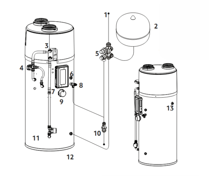
| 1 | Cold feed | 8 | T&P relief valve |
| 2 | Expansion vessel | 9 | Back-up immersion |
| 3 | Heat pump head unit | 10 | Tundish and discharge pipework |
| 4 | Circulation mode valve | 11 | Pump assembly |
| 5 | Cold water combination valve | 12 | Cold inlet |
| 6 | Hot draw | 13 | Condensate drain |
| 7 | Controller |
Hydraulic schematic
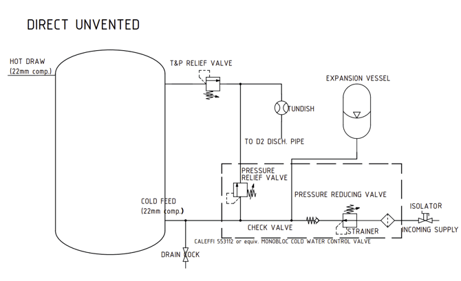
Direct unvented
Installation: General guidelines
Installation of the appliance must be carried out by a qualified engineer in accordance with prevailing and national regulations as listed below:
- Building Regulations G3
- The Building Standards (Scotland)
- The Building Regulations (Northern Ireland)
- I.E.E. Electrical Regulations (Latest edition thereof)
- UK Water Regulations
The installation area should be able to cope with the weight of the iHP (approx. 320kg for a full 250L cylinder), incoming pipes and discharge pipe when full.
Positioning of the cylinder
The position of the cylinder should suit the installation; all connections should be to the front for ease of access.
Note: Leave at least 350mm of vertical clearance above the cylinder from the top of the ducting spigots. This must include removable sections of ducting to allow for easy removal of the top cover.
Refer to the diagram and table below for space requirements.
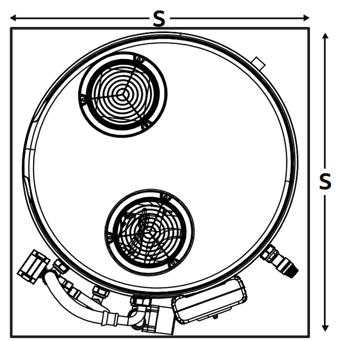
| Cylinder Capacity |
Cylinder Height |
Nominal diameter D | Space requirement S |
| L | mm |
||
| 120 | 1326 | 580 | 700 |
| 150 | 1516 | 580 | 700 |
| 180 | 1696 | 580 | 700 |
| 210 | 1886 | 580 | 700 |
| 250 | 2146 | 580 | 700 |
Unvented installations
Installers should ensure incoming mains pressure is less than 10 bar and at-least 1 bar with a minimum flow rate of 10 L/min. Local authority approval for installation of unvented systems must be granted.
Use of flux
Excessive use of flux can damage the unit and especially the valves and expansion vessel (if supplied). Avoid over-use and ensure the system is fully flushed of any debris or flux after connection.
Pipework and cold water control group
The unit should be connected using 22mm pipe to ensure adequate flow rate.
The unit is supplied with a combination valve with a set pressure of 3 bar.
An isolation valve (not supplied) should be fitted before the combination valve.
Under no circumstances should the isolating valve be fitted between the expansion vessel and the storage cylinder.
Fitting a drain valve
A drain valve should be fitted to the lowest part of the unit, The drain valve must be fitted to allow at least 80% of the cylinder’s total capacity to be drained.
Positioning the tundish
The tundish, which shows visible discharge from the relief valves, is to be in a prominent, visible and safe position away from any electrical devices. See Building Regulation G3 Discharge Requirements.
Checking the pump and T&P relief valve
The temperature and pressure relief valve is set at 7 bar and 90°C. The pump and T&P valve seals should be checked as part of commissioning.
Attention: The pump body is plastic. Use two spanners when tightening the pump compression glands to avoid cracking the pump body
Fitting the expansion vessel
The expansion vessel should be charged at 3.0 bar.
The vessel should be mounted securely to the wall or sufficient support with the fixing kit supplied.
The connection should be made between the vessel and combination valve using the included 3/4” x 22mm compression adapter.
Attention: No valves should be fitted between the combination valve and the cylinder.
Electrical: The electrical supply to the controller must be installed by a qualified electrician.
Attention: Ensure that any apertures (such as loft hatches) that the cylinder must pass through meet the minimum space requirement.
Installation: Heat Pump Head Unit
Check condensate sealing cap is fitted
The central hole in the condensate tray must be fitted with the sealing cap to prevent water ingress to the cylinder insulation. Before fitting the heat pump head unit check that this is in place.
If the cap is missing a spare is included in the installer kit. This must be fitted before mounting the head unit.
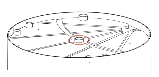
Attention: If the sealing cap is not installed before the cylinder is commissioned this will invalidate the cylinder warranty
Assembling the head unit onto the cylinder
The head unit and cylinder are delivered separately to simplify installation.
Once the cylinder is in position the head unit can be lifted onto the top of the cylinder ensuring that the hydraulic connections line up with the head unit feed assembly and that the threaded inserts in the condensate tray line up with the fixing holes.
Fix the head unit to the cylinder using the four M8x25 bolts and M8 washers provided.
Attention: The head unit weighs 33kg so requires two people to lift safely. There are two lifting loops at the front of the head unit: one on the compressor, and one on the plate heat exchanger. Remove the cover to access these. Lift using these, steadying the unit using the fan and electronic housings.
DO NOT lift by the refrigerant pipe work as this may damage the head unit and will void the warranty.
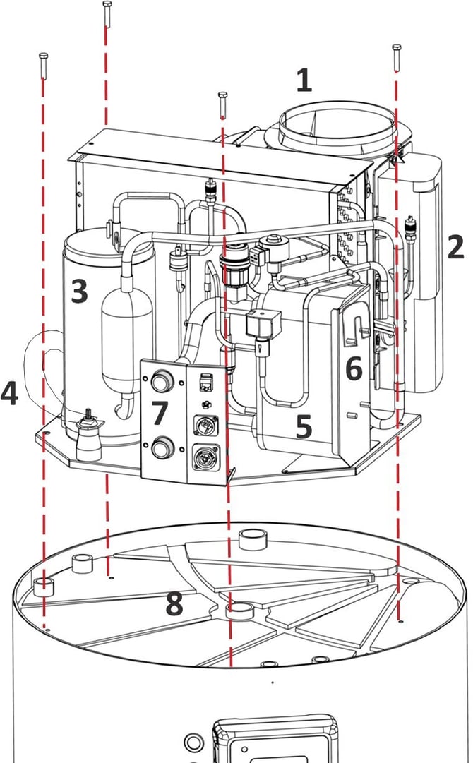
| 1 | Fan housing | 5 | Plate heat exchanger |
| 2 | Electronics housing | 6 | Plate heat exchanger lifting handle |
| 3 | Compressor | 7 | External connection panel |
| 4 | Compressor lifting handle | 8 | Condensate tray |
Heat pump supply and immersion connections
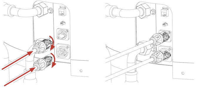
Connect the heat pump supply and immersion cables to the heat pump connector panel.
The two PowerCON connectors should be inserted then turned clockwise till they lock.
Heat pump data connections
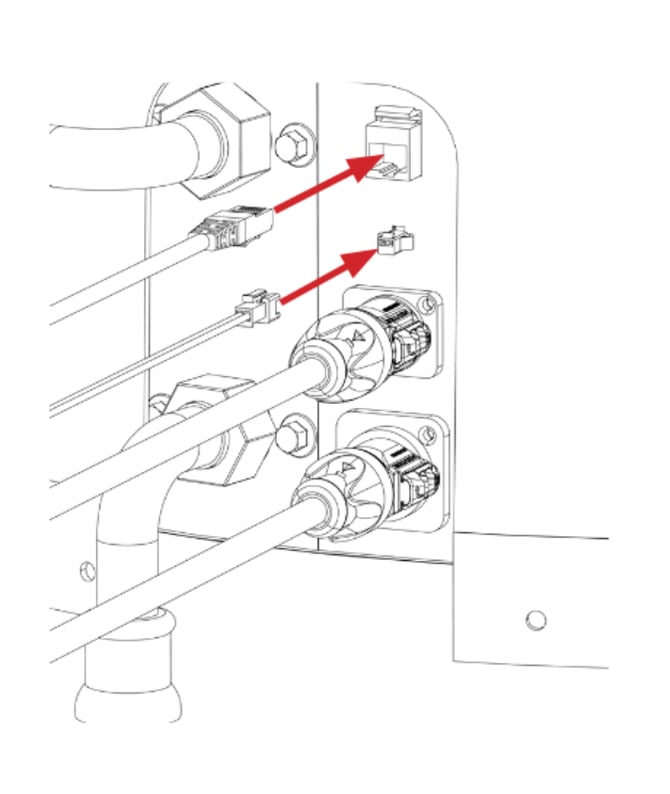
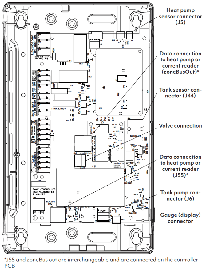
Connect the flow temperature sensor (two pin plug) and the data (RJ45) cables from the controller to the head unit connector panel.
These two cables are normally supplied already connected to the controller. If not see controller connector positions for the connector locations.
Installation: Heat Pump Head Unit Pre Plumb Kit
Fit pipe clips
Fit two 22mm brass pipe clips (supplied) to the cylinder using No.8 x 25mm self drilling screws (supplied) and 15mm nylon spacers (supplied). There are pre drilled holes in the cylinder. One (1) is just below the 3 way valve on the Full Circulation Return Assembly (2). The other is just below the top of the Head Unit Feed assembly - see next page for drawing.
Connect the Full Circulation Return Assembly
Connect the assembly to the 22mm compression gland on the cylinder as shown opposite. Secure the unit using the upper of the two pipe clips.
Connect the top port of the 3 way valve to the upper port of the head unit using the supplied 350mm flexi hose (3). Fit 3/4” fibre washers (supplied) when assembling the face seals.
Connect the Top Up Return Assembly
Connect the assembly (4) to the 22mm compression gland on the cylinder as shown opposite. Ensure the pipe is vertical when tightening the gland.
Connect the horizontal port on the 3-Way Valve to the Top Up Return assembly using the supplied 243mm flexi hose (5).
Fit 3/4” fibre washers (supplied) when assembling the face seals.


| 1 | Upper pipe clip location |
| 2 | Full Circ Return Assembly |
| 3 | Flexi hose 1(350mm) |
| 4 | Top-Up Return Assembly |
| 5 | Flexi hose 2 (243mm) |
Fit Head Unit Feed Assembly
Connect the bottom of the Head Unit Feed Assembly (6) to the 22mm compression fitting near the base of the cylinder as shown opposite.
Secure the upper part of the assembly to the cylinder using the lower of the two pipe clips (7).
Connect the remaining flexi hose (8) to the lower port of the head unit then connect the other end to the 22mm pipe at the top of the head unit feed assembly using the integral compression gland.
Note that the face seal must be connected first to ensure proper alignment.
Fit a 3/4” fibre washer (supplied) when assembling the face seal.
Do not attach the top cover until commissioning has taken place. Before use, the system will need bleeding and the bleed valve is inside the top cover.
For more information, see the Commissioning section.
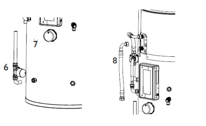
| 6 | Head Unit Feed Assembly |
| 7 | Lower pipe clip location |
| 8 | Flexi 3 (350mm 3/4” F x 22mm CM) |
Attention: It is the responsibility of the installer to ensure all compression and face seal fittings are tight and do not leak before leaving the property.
Installation: Pre Plumb Insulation
Valve Electrical Connection
Connect the valve actuator to the controller by connecting the actuator cable to the corresponding cable from the controller. This cable is normally supplied already connected to the controller. If not see Controller connector positions for the connector location.
 Pre-plumb pipework insulation
The external pre-plumb pipework, highlighted in red, should be insulated using class O insulation (not included).
The recommended thickness for class O insulation is 25mm for the best performance from your Mixergy iHP.
Installation: Heat Pump Head Cover
Installing the top cover
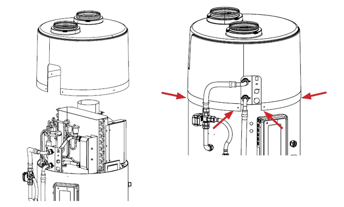
The top cover should be fitted over the head unit with the side cut-out aligned with the connector panel. The top cover is secured with four self drilling screws (included). The screws do not require pilot holes.
The locations for the screws is indicated below by the red arrows.
Do not attach the top cover until the system has been bled. For more information, see Commissioning.
Attention: Not installing the top cover mounting screws will result in air, and therefore heat, to be taken from the house. The screws help ensure the flow from the house is kept to a minimum.
Head Unit Sealing
To ensure minimal undesired exchange of air between the iHP and the installation location, the iHP has been fitted with a foam sealing kit. This sealing kit is designed to fill any gaps between the top cover, condensate tray and head unit.
When installing the head unit onto the condensate tray, there is a strip of foam already applied to the condensate tray. This foam strip will sit beneath the connector panel once the head unit is installed. The connector panel should compress the foam slightly, ensuring an air tight seal.
Attention: If the connetor panel is not making proper contact with the foam strip, air from the installation location will be drawn into the head unit.
Inset from the bottom edge of the top cover, there is a foam strip that runs around the inside perimeter. There is also additional thickess of insulating foam around the mouse hole for the connector panel. When installing the top cover, the mouse hole should be aligned such that the surrounding foam is in contact with the sides and top of the connector panel.
The top cover can then be pushed downwards, and secured in place with the screws described above.
Attention: Failure to apply downwards pressure whilst securing the top cover will result in an improper seal.
Whilst installing the top cover, attention should be paid to the seal between the fan and the top cover. The fan has a foam sealing ring on the outlet, and this sealing ring should make contact the full way around once the top cover is installed.
Installation: Heat Pump Ducting Design
Ducting Design
The iHP cylinder uses 150mm ducting for the exhaust and intake of air to the heat pump head unit. Ducting adaptors should be fitted if using 160mm ducting.
Mixergy recommends the use of Ubbink Aerfoam for round duct iHP installations. If a mixture of round and flat ducting is required Mixergy recommends Verplas Rapid Self-Seal Thermal ducting.
- Minimise the number of bends in the ducting for best efficiency.
- Intake and exhaust ports should be separated. A 1.5m separation is recommended if practical.
- If the ports have to be closer than recommended try to place the intake port above the exhaust port to minimise cross flow from exhaust to intake.
- Vertical dusting through the roof directly above the head unit, will minimise bends. A 45 degree bend can be used to either route one duct to the opposite side of the roof or separate the external terminations.
- Ducting must be insulated to stop condensation forming on the exterior of the ducts.
- Avoid flexible ducting.
- Avoid high-loss louvres for side exits. If louvres are required ensure they are appropriately oversized to minimise losses. The use of bird-beak style side exits is recommended.
- If there are any air handling ports on an opposite wall 2m or closer (iHP, MVHR etc.), placement of the intake/exhaust ports should be no closer than 3.5m.
- The recommended minimum distance from an opposite wall is 1m.
- The exhaust port should be no closer than 1m from any protruding wall or window or other opening. The same clearance should be given for open eaves.
- If installing for loft intake, ensure the intake is at least 500mm from any surface, especially any surface using Rockwool style insulation, as this will cause serious dust build up within the head unit.
Ducting Design Continued
When crafting the ducting installation, it is important to allow for future servicing of the iHP head unit. As previously mentioned on page 8, 350mm should be left above above the iHP to allow the top cover to be installed/removed. This 350mm of clearance also applies to the ducting.
The inlet and outlet ducting imedietely above the iHP should be easy to detach and remove, giving the 350mm of clearance required for servicing.
Installation: Heat Pump Head Unit Ducting Design
Attention: If installing near a conventional boiler or property operating a conventional boiler, it is important to consider the impact of the iHP on the flues and subsequent air flow in the boiler. If the iHP intake/exhaust are too close to a boiler flue, it will affect the air flow to the boiler system which could lead to incomplete combustion. There is also a risk that the iHP intake will draw combustion products into the property.
The following should be considered:
- For opposite walls under 2m away, the iHP intake/exhaust should be no closer than 3m to any boiler flue.
- The iHP intake/exhaust should be installed no closer than 2m from a protruding (perpendicular) wall containing a boiler flue.
- If installing on the same wall as a boiler flue, the intake/exhaust should be no closer than 2m to the flue. If there is an opposite wall less than 2m way, increase this distance to 3m.
- If the iHP intake/exhaust are exiting a wall, they should not be aimed directly at any vertical flues within 3m. If a vertical boiler flue is closer than 4m to the desired wall, the installer should aim to offset the iHP intake/exhaust by a minimum of 1m, while maintaining a minimum distance of 3m from the flue.
These are guidelines only. It is the responsibility of the installer to ensure that the iHP installation has no effect on the operation any boiler system in close proximity to the iHP installation.
Installation: Heat Pump Head Unit Ducting
Mixergy recommends the use of Ubbink Aerfoam for all iHP ducting installations. The design of this ducting means the losses created by typical PVC elbows are reduced by approximately 30%. This helps ensure the best performance from the iHP cylinder.
Below is a table of typical iHP ducting installations using generic PVC 150mm ducting and indicative COP figures to show the effect of different ducting designs. These COP figures are not a guarantee of performance, as there are many real world variables that will affect the achieved COP.
| Instantaneous COP |
|||||
| Duct length (m) | Straight | 2xElbow, 90° | 4 x Elbow, 90° | 2 x Elbow, 90° + 2 x Elbow, 45° |
4 x Elbow, 90° + 4 x Elbow, 45° |
| 1.00 | 3.33 | 2.84 | 2.55 | 2.75 | 2.40 |
| 5.00 | 3.27 | 2.79 | 2.51 | 2.71 | 2.36 |
| 10.00 | 3.19 | 2.74 | 2.47 | 2.66 | 2.31 |
| 15.00 | 3.10 | 2.69 | 2.42 | 2.61 | 2.26 |
| 20.00 | 3.00 | 2.64 | 2.36 | 2.57 | 2.22 |
 Mixergy recommends a maximum duct length of 20 metres. All figures shown are for total combined duct length on the inlet and outlet of the iHP.
In the example shown to the right, if the length sum of S₁, S₂, S₃ and S₄ is 10 metres, and there are two 90° elbows, E₁ and E₂, the resulting approximate COP would be 2.74.
Instantaneous COP was measured over a full reheat (full circulation mode) of the cylinder, from 10°C to 55°C, with 14°C inlet air.
If you need more in-depth information regarding fan and COP data for your installation, please contact Mixergy.
Building Regulation G3 Discharge Requirements
Discharge pipes from safety devices
As part of the requirements of Building Regulation G3 this product is factory fitted with a T&P valve, which complies with BS EN 1490. Any discharge from a water heater system should be conveyed to where it is visible but will not cause danger to persons in or about the building. The tundish and the discharge pipes should be fitted in accordance with the requirements of Building Regulation approved document G3, (England and Wales), Part P of Northern Ireland and Standard 4.9 of Scotland.
Tundish
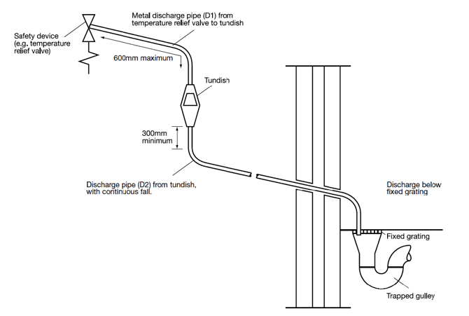
The tundish should be vertical, located in the same space as the unvented hot water storage system and be fitted as close as possible to, and lower than, the safety device, with no more than 600mm of pipe between the valve outlet and the tundish. Note: to comply with the Water Supply (Water Fittings) Regulations, the tundish should incorporate a suitable air gap.
Discharge Pipe D2
The discharge pipe (D2) from the tundish should have a vertical section of pipe at least 300mm long below the tundish before any elbows or bends in the pipework. It should be installed with a continuous fall of at least 1 in 200.
The discharge pipe (D2) should be made of metal or other material that has been demonstrated to be capable of safely withstanding temperatures of the water discharged and is clearly and permanently marked to identify the product and performance standard (e.g. as specified in the relevant part of BS 7291-1:2006).
Mixergy strongly recommends the use of metal pipework only and Mixergy does not take responsibility for any damage caused from discharges.
The discharge pipe (D2) should be at least one pipe size larger than the nominal outlet size of the safety device unless its total equivalent hydraulic resistance exceeds that of a straight pipe 9m long, i.e. for discharge pipes between 9m and 18m the equivalent resistance length should be at least two sizes larger than the nominal outlet size of the safety device; between 18 and 27m at least 3 sizes larger, and so on; bends must be taken into account in calculating the flow resistance.
| Sizing of copper discharge pipe ‘D2’ for common temperature relief valve outlet sizes | ||||
| Valve outlet size | Min size of discharge pipe D1 | Min size of discharge pipe D2 from tundish |
Max resistance allowed, expressed as a length of straight pipe |
Resistance created by each elbow or bend |
| G 1/2" | 15 mm | 22 mm | < 9 m | 0.8 m |
| 28 mm | < 18 m | 1.0 m | ||
| 35 mm | < 27 m | 1.4 m | ||
| G 3/4" | 22 mm | 28 mm | < 9 m | 1.0 m |
| 35 mm | < 18 m | 1.4 m | ||
| 42 mm | < 27 m | 1.7 m | ||
| G 1" | 28 mm | 35 mm | < 9 m | 1.4 m |
| 42 mm | < 18 m | 1.7 m | ||
| 54 mm | < 27 m | 2.3 m | ||
Discharge pipe D2
- Where a single common discharge pipe serves more than one system, it should be at least one pipe size larger than the largest individual discharge pipe (D2) to be connected.
- Any discharge should be visible at the tundish. In addition, where discharges from safety devices may not be apparent, e.g. in dwellings occupied by people with impaired vision or mobility, consideration should be given to the installation of a suitable safety device to warn when discharge takes place, e.g. electronically operated.
- The discharge pipe should not be connected to a soil discharge stack unless it can be demonstrated that the soil discharge stack is capable of safely withstanding the temperatures of the water discharged, in which case, it should contain a mechanical seal, not incorporating a water trap, which allows water into the branch pipe without allowing foul air from the drain to be ventilated through the tundish.
- If plastic pipes are used as branch pipes carrying discharge from a safety device, they should be either polybutylene (PB) or cross-linked polyethylene (PE-X) complying with national standards such as Class S of BS 7291-2:2006 or Class S of BS 7291-3:2000 respectively; and be continuously marked with a warning that no sanitary appliances should be connected to the pipe.
- Where pipes cannot be connected to the stack it may be possible to route a dedicated pipe alongside or in close proximity to the discharge stack.
An alternative approach for sizing discharge pipes would be to follow Annex D, section D.2 of BS 6700:2006 + A1:2009 Specification for design, installation, testing and maintenance of services supplying water for domestic use within buildings and their curtilages.
Plastic pipes should be joined and assembled with fittings appropriate to the circumstances in which they are used as set out in BS EN ISO 1043-1:2002.
Discharge pipework termination
Termination of discharge pipe
The discharge pipe (D2) from the tundish should terminate in a safe place where there is no risk to persons in the vicinity of the discharge.
Examples of acceptable discharge arrangements are:
- To a trapped gully with the end of the pipe below a fixed grating and above the water seal.
- Downward discharges at low level - i.e. up to 100mm above external surfaces such as car parks, hard standings, grassed areas etc. are acceptable providing that a wire cage or similar guard is positioned to prevent contact, whilst maintaining visibility.
- Discharges at high level - e.g. into a metal hopper and metal downpipe with the end of the discharge pipe clearly visible or onto a roof capable of withstanding high temperature discharges of water and 3 m from any plastic guttering system that would collect such discharges.
Termination of condensate hose
- The condensate drain is located to the right of the controller on the side of the cylinder. Approximately 2m of 20mm id flexible hosing is provided. This should be connected to a grey water drainpipe, D2 of the tundish pipe work or to a soil pipe.
- The head unit will discharge approximately 0.75L of water per hour under typical operating conditions.
- The hose should not run horizontally or create a U-bend.
- If discharging into a drain or soil pipe a U-bend should be used. The outlet of the U-bend must be below the inlet to avoid water backing up into the head unit.
- If discharging into D2 of the tundish pipe work, a swept tee should be used to prevent discharge traveling up the condensate drain hose and check that the outlet is suitable for continuous discharge.
Installation: Electrical
Electrical: Ensure all electrical supplies are switched off before making any connection to the unit.
Electrical installation must be carried out a competent electrician and be in accordance with the latest I.E.T. regulations.
External wiring
Mixergy cylinders come supplied with cable included. Any extensions to the supplied cabling should match or exceed the current and voltage ratings of the cables to be extended.
Primary supply (13A, 230-240V~, 1.5mm2 CSA)
The white 3-core (L,N,E) cable labelled ‘PRIMARY SUPPLY’ must be connected to the household’s main supply via a dedicated 16A MCB protected circuit with a 13A DP fused spur. This is the primary power supply for the control electronics and is used to power the heat pump (or immersion) when the cylinder is set to heat.
Timer control (VOLT-FREE, 10mA 80-240V~, 0.5mm2 CSA)
The black 3-core (L,N,E) cable labelled Timer Control can be used to integrate the Mixergy cylinder with any existing timers or controllers eg economy 7 timer or Hive dual channel controller. This cable detects a 80-240VAC signal and instructs the cylinder to heat unless otherwise disabled in software.
The timer control cable is attached to volt free contacts within the controller and can be safely left unterminated if not required.
Attention: Please note - All figures shown in this manual are for the R290 version of the Mixergy iHP.
Installation: electrical (PRIMARY SUPPLY)

Installation: Connectivity
Installing the powerline adapter
The Mixergy cylinder requires internet connectivity to allow for full control of the system. Connection to the cylinder can be made using the provided Ethernet to powerline adapter or by hard-wired Ethernet.
If an existing HomePlug AV powerline network is installed at the property, it is recommended to pair the cylinder with the existing network as described in the commissioning section. Powerline connectivity between the cylinder and internet router is only possible in houses where both the cylinder and adapter are powered from the same electrical phase.
- Plug the powerline adapter into a wall socket within 2m of the property’s internet router. Do not use an extension lead as this can cause connectivity issues.
- Connect the powerline adapter to the router using the included Ethernet cable.

Wiring an Ethernet connection
If a hard-wired CAT5/CAT5e/CAT6 network connection is available close to the cylinder it should be connected as follows:
Electrical: Ensure all electrical supplies are switched off before opening the cylinder controller cover.
 2. Replace the removed Ethernet cable with a suitable direct connection to the network (broadband router/switch).

Connecting the Display
 Connect the Mixergy gauge to the RJ12 (phone) socket on the lower right corner of the controller.
The gauge is supplied with two magnetic strips. One is fixed to the rear of the gauge and will allow the gauge to be fitted to the cylinder.
If the customer would like the gauge to be mounted to a non-magnetic surface the second strip should be fixed to this using the adhesive film on the back of the strip.
Current reader kit installation (available as an accessory)
Overview
If the property has solar PV panels there is an option to fit a current read-er on the mains supply to the property. This measures energy import and export. If the energy export exceeds a threshold (typically 250-500W) the controller will switch on the heat pump to use the excess energy to heat water. A standard Cat5e or Cat6 cable is used to connect the controller to the current reader. The MAS0071 kit is available as an accessory and is intended for properties with a single-phase supply.
MAS0071 single current clamp kit
- CT interface (MAS0061)
- Current clamp (MEC0029) x 1
- Mounting hardware (VHB pad, screws x 2, wall plugs x 2)
- 1 m Ethernet cable x 1, 2m Ethernet cable x1
Installing the current reader - single version
Positioning the CT interface
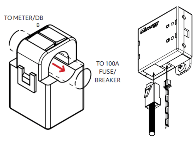
The CT interface must be placed within 300mm of the household’s incoming mains supply cabling.
The CT interface should be fixed to the wall with the two provided screws using the case mounting holes as pictured below.
Installation of the current clamps
The current clamp should be attached around the neutral (blue/black) cable on the incoming mains supply with the arrow pointing towards the incoming supply 80/100A main fuse or breaker.
If this is impractical it can be fitted round the live (brown/red) cable with the arrow pointing away from the incoming supply.
The current clamp must then be plugged into the single CT interface as pictured.
Connecting to the controller - single phase
Connection of the CT interface to the controller
The CT interface should be connected to the controller using pin to pin cat5e or cat6 Ethernet cables.Ensure that the cable used contains all 4 twisted pairs (8 conductors).
NOTE: While Ethernet cable is used for this connection, the communication protocols used are not compatible with standard networking hardware and the connection between the controller and clamp must be direct (i.e. no network switches or routing equipment is to be fitted in between)
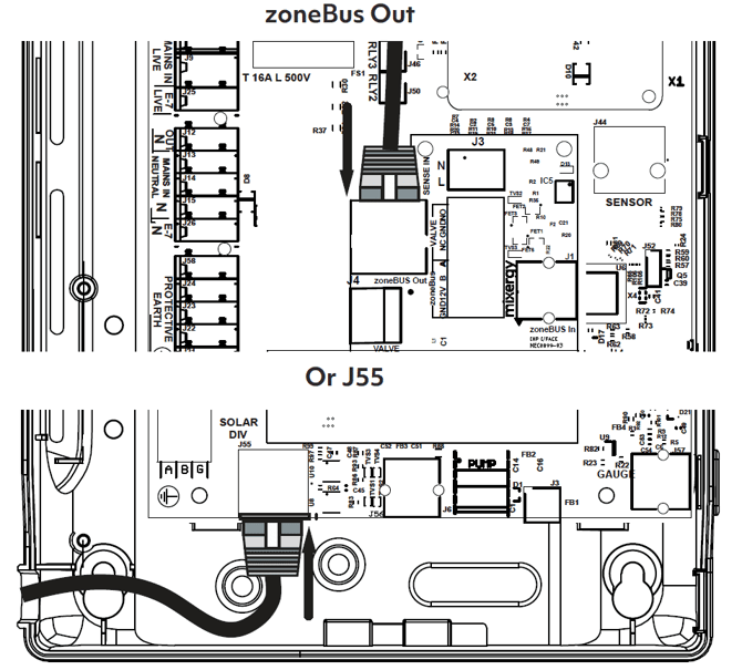
Remove the controller lid and connect one end of the cable to J55 at the lower left corner of the controller circuit board or to the zoneBus Out connector on the mezzanine board. The other connector is used to control the heat pump and should already be connected.
Connect the other end to the RJ45 connector on the single CT interface as shown on the previous page.
Controller connector positions
Commissioning
Fill and bleed the system
- Ensure the drain on the cold feed pipework is closed.
- Before turning on the mains supply to the cylinder a hot water tap should be opened, preferably on the same floor or the floor below where the cylinder is located.
- Check the pre-charge in the expansion vessel and ensure it is at least 3 bar. Note actual pressure on label on expansion vessel.
- Turn on the supply and fill until water appears at the hot tap. Continue to flush the system until all debris has been removed.
- Close the hot water tap.
- Check all joints for leaks, even those not having been altered especially when replacing a vented water heater.
- Ensure water flow is obtained at each hot water outlet expelling any air within the pipework. Once finished, close all hot water outlets.
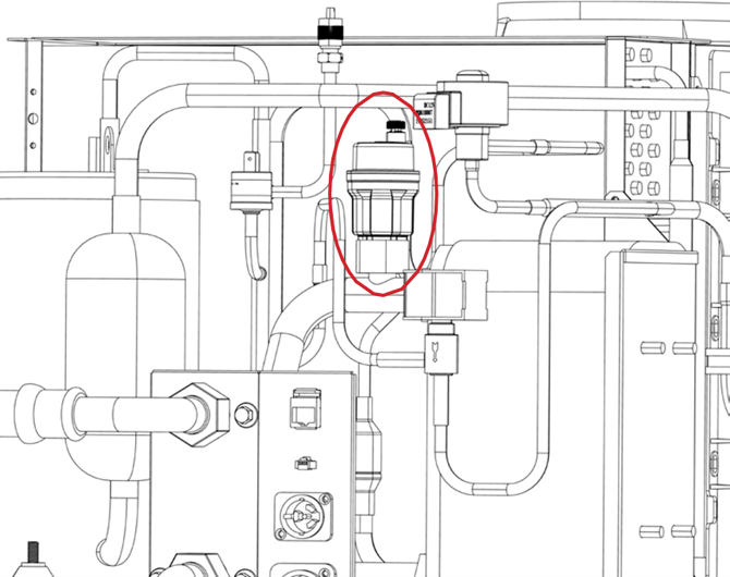
- Locate the auto air vent on the head unit (highlighted in red below) and loosen the cap. Air will be released from the top of the system. The cap can be left loose on the air vent. Do not remove the cap.
- Open temperature and pressure relief valve to ensure proper discharge and check after closing that valve is not dripping.
- Open expansion relief valve to ensure proper discharge and check after closing that valve is not dripping.
- Check that the discharge pipework is free from debris and is transporting the water away to waste effectively.
- Switch on the supply to the Mixergy iHP cylinder and check for correct operation.
- Connect the cylinder to the internet by pairing to the included powerline adapter. See Installation: connectivity and Commissioning more information. The Network LED will light when the system is connected to the Mixergy server.
Attention: Do not switch the system on unless the cylinder is completely filled with water.

On power up the tank controller runs a series of tests and displays the results on the gauge.
Note that this will only run when the main controller has booted up which takes approximately 50 seconds.
Check that no LEDs light red and that the bottom seven LEDs light green
The picture to the left shows the meaning of each LED.
Note that if a voltage is applied to the Remote Control input the Remote Control LED will light green rather than blue.
Check that all buttons (boost UP, boost DOWN and power) work correctly.
For further information on gauge operation please reference the Mixergy iHP User Guide.
Changing heating mode
All Mixergy systems leave the factory in full circulation mode. If you wish to permanently enable top-up mode, this can be achieved in a number of ways:
- If the system is connected to the internet the heating mode can be changed by the installer using the Mixergy Enterprise Installer app or by the user via the standard Mixergy app.
- Alternatively the heating mode can be set by holding the boost UP and boost DOWN buttons simultaneously. The display will light white to acknowledge that you have entered this mode. To change the heat source, let go of the buttons once any of the display LEDs has changed to the required colour (BLUE for Full Circulation, RED for top-up). The display will then flash either blue or red to indicate the new default heat source. Switch the cylinder off and on (power cycle) for the change to take effect.
Please note that any heat source that is set while the cylinder is offline will be overwritten once the cylinder establishes an internet connection, please ensure that the default heat source is set correctly on the app once the system is fully connected.
Status LED error codes
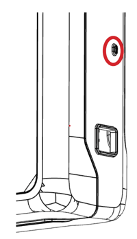
If the system is not behaving as expected, please check the status LED on the side of the controller enclosure and contact your local Mixergy Technical Support team:
- Flashing green: system OK
- Solid green/red: system updating (DO NOT REMOVE POWER)
- Very slow flashing red (once every two seconds): temperature sensor problem
- Slow flashing red (once a second): no gauge detected
- Fast flashing red (twice a second): energy measurement issue
- Very fast flashing red (five times a second): main processor issue
Pairing the cylinder and connecting to the internet
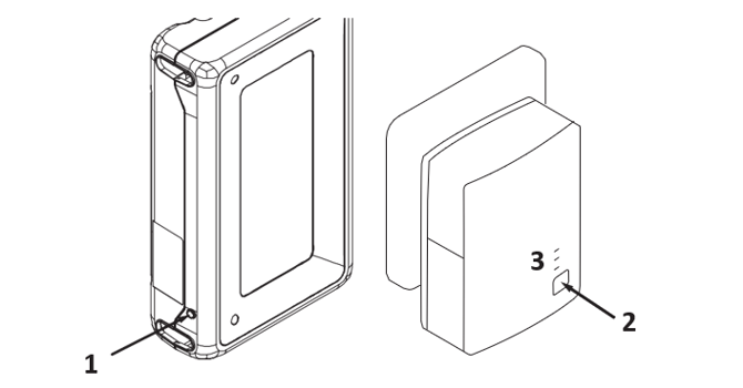
If the cylinder does not automatically pair to the powerline adapter or connect to an existing homeplug AV network is desired, please follow the steps below to pair the cylinder to the network.
- Use a thin tool to depress and hold the Pair button (1) on the lower left corner of the controller for 1 - 2 seconds.
- Depress the pair button (3) on the powerline adapter for 1-2 seconds within 2 minutes of step 2.
- Observe all 3 LEDs light green on the powerline adapter. The lower (network) LED will flash when there is network traffic. The others should be solid.
Refer to the Mixergy iHP User Guide and FAQs for further guidance.
Attention: The cylinder must be registered and connected online in order to validate the manufacturer’s 25 yr warranty.
Draining the cylinder
- Switch off the supply to the iHP controller and any other heat sources.
- Switch off the water at the mains.
- Open nearest hot tap.
- Open drain to start draining the
To re-fill follow the commissioning instructions.
Flushing the cylinder
To flush out the system, drain the unit as above, fill and repeat.
If after recharging the expansion vessel the cylinder is still discharging, it may be due to cross-flow - ensure appropriate check valves are fitted. The pressure reducing valve, one of the relief valves, or the expansion vessel may have failed. The component should be identified and replaced by one supplied by Mixergy.
Replacement parts
Do not attempt to repair or replace any parts of the Mixergy cylinder unless you are a trained operative. If you suspect a fault or a replacement part is needed, please contact Mixergy directly.
To determine the correct parts for your system, please ensure you have your cylinder MX number which can be found on the nameplate located at the front of the cylinder.
|
Part description |
Part no. |
| Immersion stat | MEL0018 |
| Pump assembly | MAS0092/93/94 |
| Controller | MAS0095 |
| Guage | MAS0043 |
| Head unit | MEL0082 |
| 3-way ball valve | MME0217 |
Servicing and Maintenance
Annual Maintenance
All annual maintenance and service checks should be performed by a competent operative.
If this system is not protected under an active Mixergy Care subscription, failure to maintain this system in accordance with these instructions will invalidate the manufacturer’s warranty.
A record should be kept on the service record found in the physical booklet.
We would recommend a service program is arranged on installation of the cylinder.
Annual service checks
- Expansion relief valve - manually open the twist cap and check that the water is discharged and runs clearly through the Tundish and out at the final discharge point. Ensure that the valve re- seats/re-seals itself.
- Pressure & temperature relief valve - repeat the above. Ensure that the valve re-seats/re-seals itself.
- Strainer—Turn off the mains. There will be a small amount of residual water in the pipework. Remove the cartridge from the Pressure-Reducing Valve, clean the Strainer, and replace it.
- Expansion vessel - check pressure via the valve on top of the vessel which is located under the plastic cap. Ensure pressure is 3 Bar. Vessel can be recharged if required as per 'Expansion vessel check and re-charging' section
- Head unit - Remove the top cover and blow out the radiator with compressed air to remove dust/debris buildup.
Disassociating an account
If a new owner or tenant is moving into the property and the user of the account tied to the cylinder needs to be changed, the new tenant will have to disassociate the cylinder from the existing account before registering. This can be performed by pressing and holding the boost down and power buttons for approximately 15 seconds.
De-scaling loop
Occasionally, the Mixergy iHP may need the heat pump heat exchanger de-scaling.
- To de-scale the unit, switch off the supply and drain the cylinder to below the lower end of the head unit feed flexi (1).
- Disconnect the two flexi hoses from the heat pump unit.
- Connect a reservoir and pump to the heat pump connections (2) and (3).
- Pump de-scaling fluid through the heat exchanger for an hour.
- Drain the de-scaling fluid from the heat exchanger and flush with water for a further 5 minutes to ensure all the de-scaling fluid has been removed.
- Disconnect the reservoir and pump.
- Reconnect the two flexi hoses disconnected in step 2 and re-fill the cylinder.
- Bleed and test the system as described in Commissioning.
- The de-scaling procedure is now complete.
Attention: After descaling, it the responsibility of the installer to ensure ensure proper functionality of the iHP.

| 1 | Head unit feed flexi hose |
| 2 | Heat pump return connector |
| 3 | Heat pump feed connector |
Previous versions

