Download the current version
Watch how to set the heat pump interface
Contents
- About this module
- Included items
- Exchanger performance graphs
- Installation: Heat Transfer Module
- Hydraulic schematics
- Installation: Heat Pump Electrical Interface
- Installation: Commissioning
- Troubleshooting
- Draining the cylinder
- Replacement parts
About this module
The Mixergy Heat Pump Integration Pack is designed to allow for integration of any Mixergy cylinder with both low and high-temperature heat pumps.
The pack contains two main units:
The Heat Transfer Module incorporates a high surface area plate heat exchanger and circulator pump to enable high-performance heat transfer between the heat pump and cylinder. This module replaces a traditional coil and can provide better volumetric efficiency, reheat speed, heat pump performance and serviceability than a conventional system.
The Heat Pump Interface provides an electrical interface between the heat pump DHW system and the Mixergy controller.
Technical data
| Exchanger construction | Copper brazed 304 SS |
| Exchanger rating* | 44 kW |
| Exchanger max. primary flow rate | 65 L/min (3.8 m³/hr) |
| Exchanger connections | 3/4” ISO-G (BSPP) M |
| Exchanger max. primary flow temperature | 80 °C |
| Exchanger equivalent coil surface area** | 3 m² |
| Exchanger max. working pressure (indirect) | 2.0 MPa (20 bar) |
| Circular pump rating | 230-240 V~ 10-50 W |
* Tested at 80 C, 15 L/min primary flow as per BS EN 12897-2016
** Equivalently performant coil surface area for SAP 10 calculations
Included items
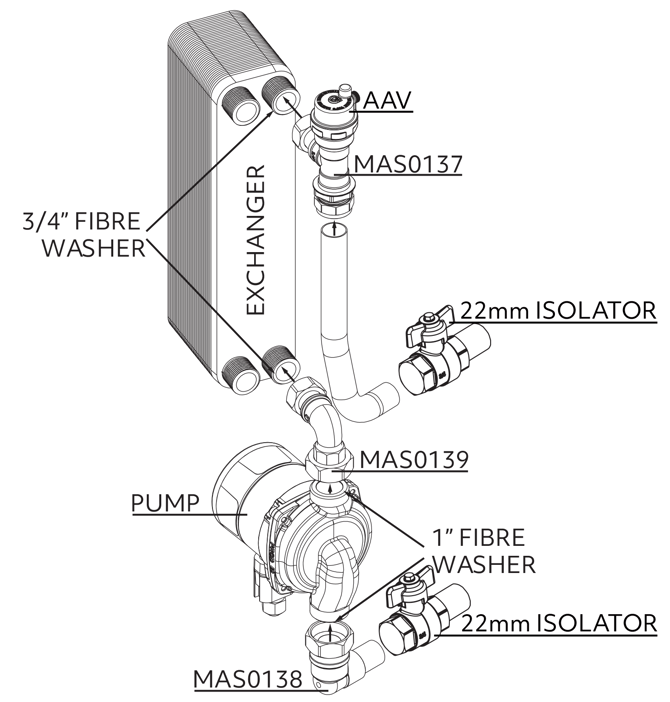
- Heat exchanger module complete with pipework, fittings (MAS0137, MAS0138, MAS0139), exchanger, AAV and pump
- 2x 22mm compression nuts and olives
- 2x 22mm isolator valves and pipe stubs
- Installation guide
- Insulating jacket for exchanger
- Heat pump interface
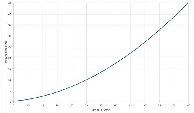
Exchanger performance graphs
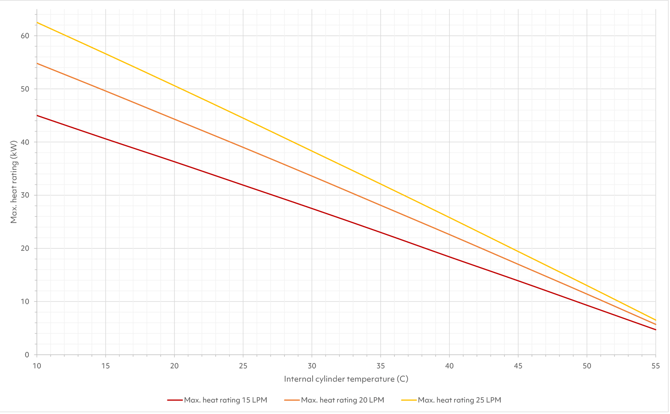
Performance given at 60 C, 15/20/25 L/min primary flow.
Installation: Heat transfer module
1. Drain hot water system if it is currently filled, refer to the back of this booklet for specific guidance on draining the hot water cylinder.
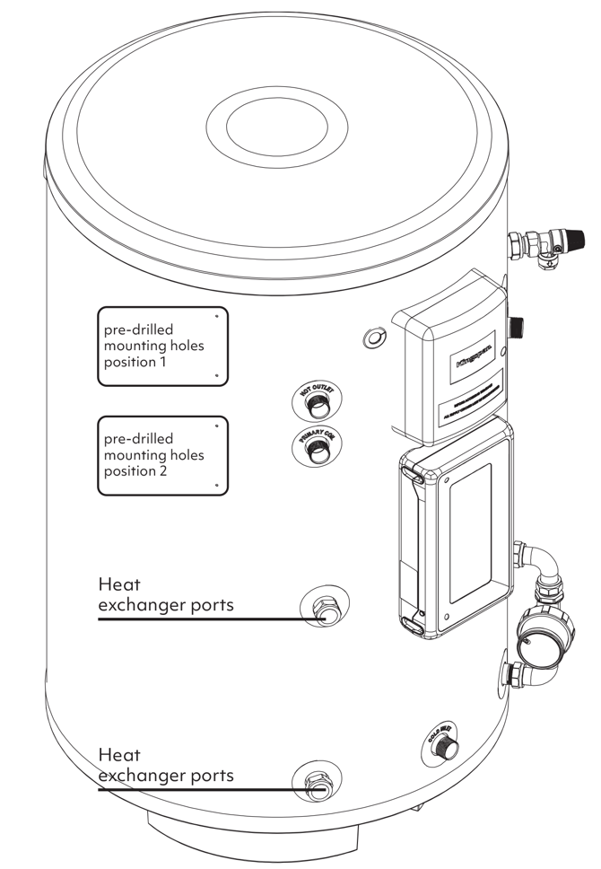
2. Remove blanking caps from cylinder heat exchanger ports and replace with included compression nuts and olives.
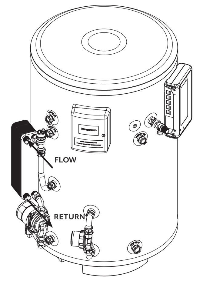
3. Assemble and orient the Heat Transfer Module as pictured.
4. (OPTIONAL) Fit 22mm isolators to the heat exchanger ports using supplied pipe stubs.
5. Push the assembly onto the cylinder.
 IT IS RECOMMENDED TO FIT THE SUPPLIED 22mm ISOLATOR VALVES BETWEEN THE EXCHANGER ASSEMBLY AND THE HEAT EXCHANGER PORTS WHEN POSSIBLE FOR EASE OF SERVICE.
6. Align exchanger assembly and tighten compression fittings. Ensure all fittings on the cylinder are tight before filling.
7. Plumb the primary circuit flow and return as pictured.
8. Refill the system with water, ensure the air vent cap is loosened to allow the system to be purged of air during filling.
9. Close the air vent cap.
10. Fit the exchanger installation jacket and supplied lagging to exposed pipework.
IT IS THE INSTALLER’S RESPONSIBILITY TO ENSURE THE ASSEMBLY IS FULLY SEALED BEFORE LEAVING THE SITE.
For 120L units and in some cases where limited space or pre-existing pipework obstruct the normal mounting position of the exchanger assembly, it may be required to mount the assembly a small distance away from the cylinder. In this situation, please follow the guidance below:
- Ensure that a minimum of 22mm pipework is used to connect the exchanger assembly to the heat exchanger ports on the cylinder. Do not exceed more than 2m of additional pipework and reduce the number of bends in the pipework to a minimum.
- Ensure the exchanger assembly is adequately supported with a minimum of 3 wall mounted pipe clips within 300mm of the assembly.
- Ensure all pipework running to and from the assembly is fully lagged.
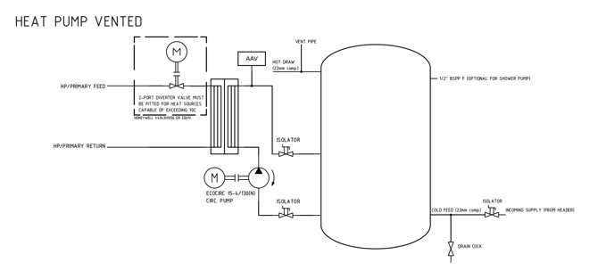
- Ensure the orientation and plumbing of the installed pipework matches that of the hydraulic schematic below.
Hydraulic schematics

Installation: Heat Pump Electrical Interface
The Heat Pump Electrical Interface allows the Mixergy tank to call for heat from the outboard Air or Ground Source Heat Pump (ASHP or GSHP) using the heat pump’s existing thermal probe or switched live input. There are two installation options:
Thermal Probe Interface (recommended)
For all new heat pump installations, we recommend this approach.
Resistor Switch Option (legacy)
For legacy installs where there is no temperature probe available (note we recommend that this is sourced if possible and the Thermal Probe Interface option is pursued.
ENSURE ALL ELECTRICAL SUPPLIES ARE SWITCHED OFF BEFORE MAKING ANY CONNECTION TO THE UNIT. ELECTRICAL INSTALLATION MUST BE CARRIED OUT BY A COMPETENT ELECTRICIAN AND BE IN ACCORDANCE WITH THE LATEST I.E.E. REGULATIONS.
1. Remove the front cover of the HP interface.
2. Mount the PV switch either to the side wall of the cylinder (using the included self-tapping screws at either position 1 or 2 as shown above) or to a nearby wall (using the included plastic spacers and screws).
-12-1.png?width=300&height=300&name=MDC0008-04-Mixergy-Heat-Pump-Installation-Guide-(HP-Interface-MK2)-12-1.png)
-12-2.png?width=300&height=300&name=MDC0008-04-Mixergy-Heat-Pump-Installation-Guide-(HP-Interface-MK2)-12-2.png)
IN THE CASE OF A 120L CYLINDER, IT IS RECOMMENDED TO FIT THE HEAT PUMP INTERFACE AT POSITION 1 TO ALLOW SPACE FOR THE EXCHANGER ASSEMBLY.
 ENSURE ALL ELECTRICAL SUPPLIES ARE SWITCHED OFF BEFORE MAKING ANY CONNECTION TO THE UNIT. ELECTRICAL INSTALLATION MUST BE CARRIED OUT BY A COMPETENT ELECTRICIAN AND BE IN ACCORDANCE WITH THE LATEST I.E.E. REGULATIONS.
How the electrical interface works
The Mixergy Cylinder Controller indirect relay is connected to the HP interface unit via the controller INDIRECT cable.
A 240Vac supply, fused at 3A, should be connected to the SUPPLY terminals in the HP interface unit in order to power the included circulator pump. The INDIRECT and STAT cables from the Mixergy Controller should be connected to the INDIRECT terminals following
the wiring details below.
When the Mixergy cylinder makes a call for heat, 240VAC will be switched to the PUMP terminals on the HP interface unit. The SW_L terminals also switch and can be used to turn on a heat pump with a switched live control input and/or to control a zone valve if required.
Temperature sensor interface
The Heat Pump Interface allows the Mixergy tank to call for heat from the Heat Pump (ASHP or GSHP) using the heat pump’s existing thermal probe. There are two installation options:
Thermal Probe Interface (recommended)
For all new heat pump installations, we recommend this approach. The Heat Pump DHW temperature probe should be mounted on the pipe between pump and heat exchanger and connected to the SENSOR1 connector on the HP interface unit.
The Heat Pump DHW temperature sensor input should be connected to the HEATPUMP1 connector on the HP interface unit.
When the controller calls for heat, the temperature probe is connected to the Heat Pump DHW sensor input and heats normally.
When the cylinder has reached the target temperature, the Heat Pump’s DHW sensor input is switched to the HOT resistor ladder, which is set to simulate a temperature of ~65C.
Resistor Switch Option (legacy)
For legacy installs where there is no temperature probe available (note we recommend that this is sourced if possible and the Thermal Probe Interface option is pursued.
This works similarly to the first option except that when the controller calls for heat the Heat Pump DHW sensor input is connected to the COLD resistor ladder, which is set to simulate a temperature of ~35C.
Recommended installation (DHW Sensor)
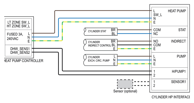
For heat pumps with a DHW sensor input, the recommended installation is as follows:
- Connect cylinder indirect control cable GREEN/YELLOW to HP interface INDIRECT E.
- Connect cylinder indirect control cable BLACK to HP interface INDIRECT COM.
- Connect cylinder indirect control cable BROWN to HP interface INDIRECT NO.
- Connect cylinder indirect control cable GREY to HP interface INDIRECT NC.
- Connect cylinder high limit stat. cable BROWN to HP interface STAT COM.
- Connect cylinder high limit stat. cable BLUE to HP interface STAT NC.
- Connect cylinder exchanger circ. pump L, N, E to HP interface PUMP L, N, E.
- Connect heat pump 3A supply L, N, E to HP interface SUPPLY L, N, E.
- Connect HP interface H/PUMP1 terminals 1,2 to heat pump DHW sensor terminals via a length of 2-core cable. Conductor orientation does not matter. If the heat pump sensor interface has more than 2 terminals, please contact Mixergy directly for further guidance.
- Connect the sensor supplied by the heat pump manufacturer to the SENSOR1 terminals. Fit the sensor to the pipe connecting pump and heat exchanger ensuring it is well insulated.
Full schematics for this installation can be found below.
ENSURE 2-CORE CABLE USED FOR SENSOR INTERFACE HAS A MINIMUM CSA OF 0.25 mm².
Alternate installation (Modified S-PLAN)
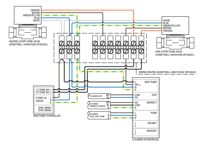
For heat pumps with a dedicated DHW ON switched live input or a configurable high temperature (HT) zone switched live input, the recommended installation is as follows:
- Connect cylinder indirect control cable GREEN/YELLOW to HP interface INDIRECT E.
- Connect cylinder indirect control cable BLACK to HP interface INDIRECT COM.
- Connect cylinder indirect control cable BROWN to HP interface INDIRECT NO.
- Connect cylinder indirect control cable GREY to HP interface INDIRECT NC.
- Connect cylinder high limit stat. cable BROWN to HP interface STAT COM.
- Connect cylinder high limit stat. cable BLUE to HP interface STAT NC.
- Connect cylinder exchanger circ. pump L, N, E to HP interface PUMP L, N, E.
- Connect heat pump 3A supply L, N, E to HP interface SUPPLY L, N, E.
- Connect DHW 2-port diverter valve WHITE to 3A supply L.
- Connect DHW 2-port diverter valve BLUE to 3A supply N.
- Connect DHW 2-port diverter valve GREEN/YELLOW to 3A supply EARTH.
- Connect DHW 2-port diverter valve BROWN to HP interface SW_L NO.
- Connect DHW 2-port diverter valve ORANGE to heat pump DHW ON/HT ZONE ON.
Full schematics for this installation can be found below.
ENSURE 3-CORE CABLE USED FOR CIRCULATOR PUMP HAS A MINIMUM CSA OF 0.5 mm² AND A MINIMUM VOLTAGE RATING OF 240 VAC.
Installation: commissioning
- Set the DIP switches SW1, SW2 and SW3 in the top right corner of the HP interface board to select the correct heat pump. See next section for details of settings for particular heat pumps.
- Ensure the heat pump’s HT zone/DHW water heating is unscheduled (i.e. always available) otherwise this can cause schedule conflicts with the Mixergy app.
- Ensure that any time constraints on DHW priority are removed. These can be reinstated once the 0-100% reheat time has been observed.
- Set the Mixergy cylinder default heat source to heat pump mode. This can be done in the web/phone app or directly on the cylinder gauge by holding both the boost up and down buttons and releasing once the display lights green.
- Boost the cylinder and check for correct operation (i.e. a call for heat is made, circulator pump and heat pump begin running, cylinder starts to heat).
- Check that cancelling the boost switches off the heat pump and circulator pump. NOTE: To prevent short cycling and possible damage, the heat pump state can only be changed every fifteen minutes.
The heatpump interface uses three DIP switches to set a resistance that emulates the heat pump’s temperature sensor.
When the Mixergy controller calls for heat the COLD resistor ladder and the SENSOR1 connector are connected to the H/PUMP1 connector.
The top switch (1) on SW1 connects the HOT resistor ladder so should be ON unless using the OPT sockets to fit leaded resistors.
If using ‘legacy’ mode set SW2-1 to ON to connect the COLD resistor ladder.
The resistance is changed by turning switches on or off. Each switch shorts out a resistor so to add a particular value to the resistance, turn the corresponding switch OFF. For example, to set a resistance of 610 ohms turn all switches ON apart from 4 (200) and 5 (410).
The resistor values corresponding to each switch are shown on the PCB silk screen.
The HOT resistance can be set between 0 and 100kΩ in 50Ω steps. The COLD resistance can be set between 0 and 400kΩ in 50Ω steps.
The tables below give details for some common heat pumps. Contact Mixergy technical support if your heat pump is not listed.
Resistances can be checked by measuring between the COM and HOT or COLD test points next to the large relay. This allows the setting to be checked while the unit is unpowered.
-19.png?width=670&height=367&name=MDC0008-04-Mixergy-Heat-Pump-Installation-Guide-(HP-Interface-MK2)-19.png)
| Switch No. | Resistance | Mitsubishi | LG | Vaillant | |||
| Hot | Cold | Hot | Cold | Hot | Cold | ||
| 1* | Enable | ON | OFF | ON | ON | ON | ON |
| 2 | 50R | OFF | ON | ON | ON | ON | OFF |
| 3 | 100R | ON | OFF | ON | OFF | ON | OFF |
| 4 | 200R | ON | OFF | OFF | OFF | OFF | OFF |
| 5 | 410R | OFF | ON | ON | ON | OFF | ON |
| 6 | 820R | OFF | ON | OFF | ON | ON | ON |
| 7 | 1K64 | ON | ON | ON | ON | ON | OFF |
| 8 | 3K3 | ON | OFF | ON | OFF | ON | ON |
| 9 | 6K8 | ON | ON | ON | ON | ON | ON |
| 10 | 13K | ON | ON | ON | ON | ON | ON |
| 11 | 26K | ON | ON | ON | ON | ON | ON |
| 12 | 51K | ON | ON | ON | ON | ON | ON |
| 13** | 100K | - | ON | - | ON | - | ON |
| 14** | 200K | - | ON | - | ON | - | ON |
| Total resistance | 1280 | 3600 | 1020 | 3600 | 610 | 1990 | |
| Switch No. | Resistance | Hitachi | Nibe | Samsung | |||
| Hot | Cold | Hot | Cold | Hot | Cold | ||
| 1* | Enable | ON | ON | ON | ON | ON | ON |
| 2 | 50R | ON | ON | OFF | OFF | OFF | ON |
| 3 | 100R | OFF | ON | ON | OFF | ON | OFF |
| 4 | 200R | OFF | ON | OFF | OFF | ON | ON |
| 5 | 410R | ON | ON | OFF | ON | ON | ON |
| 6 | 820R | ON | ON | ON | ON | ON | OFF |
| 7 | 1K64 | ON | ON | ON | OFF | OFF | ON |
| 8 | 3K3 | OFF | ON | ON | ON | OFF | OFF |
| 9 | 6KB | ON | ON | ON | ON | ON | OFF |
| 10 | 13K | ON | OFF | ON | ON | ON | OFF |
| 11 | 26K | ON | ON | ON | ON | ON | OFF |
| 12 | 51K | ON | ON | ON | ON | OFF | ON |
| 13** | 100K | - | ON | - | ON | - | OFF |
| 14** | 200K | - | ON | - | ON | - | ON |
| Total resistance | 3600 | 13000 | 660 | 1990 | 55990 | 150020 | |
| Switch No. | Resistance | Daikin high temp | Daikin low temp | PT1000 | |||
| Hot | Cold | Hot | Cold | Hot | Cold | ||
| 1* | Enable | ON | ON | ON | ON | ON | ON |
| 2 | 50R | ON | OFF | OFF | OFF | ON | ON |
| 3 | 100R | OFF | ON | ON | OFF | ON | OFF |
| 4 | 200R | OFF | OFF | OFF | OFF | ON | OFF |
| 5 | 410R | OFF | ON | ON | ON | OFF | ON |
| 6 | 820R | ON | ON | OFF | ON | OFF | OFF |
| 7 | 1K64 | ON | OFF | OFF | OFF | ON | ON |
| 8 | 3K3 | OFF | OFF | OFF | ON | ON | ON |
| 9 | 6KB | ON | OFF | ON | ON | ON | ON |
| 10 | 13K | ON | OFF | OFF | OFF | ON | ON |
| 11 | 26K | ON | ON | OFF | OFF | ON | ON |
| 12 | 51K | ON | ON | ON | OFF | ON | ON |
| 13** | 100K | - | ON | - | ON | - | ON |
| 14** | 200K | - | ON | - | OFF | - | ON |
| Total resistance | 4010 | 24990 | 45010 | 291990 | 1230 | 1120 | |
| Switch No. | Resistance | Midea | Panasonic / (Nibe or Vaillant) | Ecoforest / Viessman | |||
| Hot | Cold | Hot | Cold | Hot | Cold | ||
| 1* | Enable | ON | OFF | ON | OFF | ON | OFF |
| 2 | 50R | OFF | ON | ON | OFF | OFF | ON |
| 3 | 100R | OFF | ON | OFF | ON | ON | ON |
| 4 | 200R | OFF | OFF | OFF | OFF | ON | OFF |
| 5 | 410R | OFF | ON | OFF | OFF | ON | ON |
| 6 | 820R | OFF | ON | ON | OFF | OFF | ON |
| 7 | 1K64 | OFF | ON | ON | ON | OFF | ON |
| 8 | 3K3 | ON | ON | ON | ON | ON | ON |
| 9 | 6KB | OFF | OFF | ON | ON | ON | OFF |
| 10 | 13K | ON | ON | ON | ON | ON | ON |
| 11 | 26K | ON | OFF | ON | ON | ON | ON |
| 12 | 51K | ON | ON | ON | ON | ON | ON |
| 13** | 100K | - | ON | - | ON | - | ON |
| 14** | 200K | - | ON | - | ON | - | ON |
| Total resistance | 10020 | 33000 | 710 | 1480 | 2510 | 7000 | |
| Switch No. | Resistance | ATAG | Dimplex | ||||
| Hot | Cold | Hot | Cold | ||||
| 1* | Enable | ON | OFF | ON | OFF | ||
| 2 | 50R | OFF | ON | OFF | ON | ||
| 3 | 100R | ON | ON | OFF | ON | ||
| 4 | 200R | ON | OFF | ON | OFF | ||
| 5 | 410R | ON | ON | OFF | ON | ||
| 6 | 820R | OFF | ON | OFF | ON | ||
| 7 | 1K64 | OFF | ON | OFF | ON | ||
| 8 | 3K3 | ON | ON | ON | ON | ||
| 9 | 6KB | ON | OFF | ON | OFF | ||
| 10 | 13K | ON | ON | ON | ON | ||
| 11 | 26K | ON | ON | ON | ON | ||
| 12 | 51K | ON | ON | ON | ON | ||
| 13** | 100K | - | ON | - | ON | ||
| 14** | 200K | - | ON | - | ON | ||
| Total resistance | 2510 | 7000 | 3020 | 7000 | |||
* SW1 position 1 should be ON unless using the OPT leaded resistor sockets. SW2 position 1 should be OFF unless using the COLD resistor ladder to simulate the water temperature in legacy mode
** Switch number 13 is SW3-1, switch number 14 is SW3-2.
Troubleshooting
No call for heat is made
If no call for heat is made and the cylinder is instead energizing the primary immersion, ensure that the cylinder has been set to operate with a default heat source set as ‘heat pump’. If the cylinder is offline then this change may require a reboot to take effect. If a call for heat is being made by the cylinder but there is no response from the circulator pump, ensure that a 240VAC supply has been provided to the assembly junction box. If a call for heat is made and the circulator powers but the heat pump does not respond, double-check the wiring integration with the heat pump along with the heat pump controller setup - refer to the heat pump’s installation manual for further guidance.
Heat pump reporting strange temperatures
If the heat pump DHW sensor reading is either in an error state or reporting values outside of the expected range, then the heat pump may be set to the wrong sensor type. If the heat pump accepts multiple different types of temperature sensor, try checking the heat pump manual for guidance on changing the sensor type. If no such function exists, please contact Mixergy directly for further support.
Slow charging
If the cylinder is charging slowly when charging via heat pump, ensure that the heat exchanger circulator pump is running and that there is adequate flow rate through the primary side of the exchanger.
Electrical fault
If an electrical fault of the controller is suspected or the electrical system does not operate as expected, please contact Mixergy directly
Intermittent charging
If the cylinder is only able to charge some of the time when a call for heat is made or charging is out of sync with calls for heat, this indicates either a scheduling conflict or a wiring integration issue. If the former is suspected, please ensure that the heat pump controller’s DHW generation is unscheduled. If the latter is suspected, double-check the wiring. If a solution cannot be found, please contact Mixergy directly.
Immersion is being used in heat pump mode
The cylinder will auto-detect if the heat pump has reached a temperature ceiling below the set temperature of the cylinder (for example if the heat pump reaches a maximum of 45 C with a cylinder set temperature of 55 C). If this is detected, the immersion will be switched on in order to satisfy the temperature difference. If this behaviour is undesirable, the set temperature of the cylinder should be adjusted down and the flow temperature of the heat pump adjusted up. Please note that a set temperature of less than 50 C is not permitted for sanitary reasons.
Other issues
If any other issues are suspected, please contact Mixergy directly for further support.
Draining the cylinder
- Switch off the controller, boiler and any other heat sources.
- Switch off water at the mains.
- Open the nearest hot tap.
- Open the drain to start draining the cylinder.
Replacement parts
Do not attempt to repair or replace any parts of the Mixergy cylinder unless you are a trained operative. If you suspect a fault or a replacement part is needed, please contact Mixergy directly.
| Part description | Part no. |
| Heat exchanger assembly | MAS0003 |
| Upper fitting assembly | MAS0137 |
| Middle fitting assembly | MAS0139 |
| Lower fitting assembly | MAS0138 |
| Circulator Pump | MEL0021 |
| Heat exchanger | MME0072 |
| Heat exchanger jacket | MME0054 |
| AAV | MME0123 |
| Heat pump interface MK2 | MAS0193 |
Previous Version
- Version 2 (PDF, 1.1MB)