MDC0001: Mixergy X Installation and Servicing Manual
The installation and servicing manual for Mixergy X and Solar X stainless steel hot water cylinders. Version MDC0001-18.
Download the current version of the Mixergy X Installation and Servicing Manual
Contents
- Safety
- Included items and technical data
- Dimensions and clearance
- Hydraulic installation
- Discharge pipework
- Electrical installation
- Commissioning
- Troubleshooting
- Draining the cylinder
- Service instructions
- Unlinking an account
- Replacement parts
- Disposal
Safety
This equipment must be connected to a protective earthing (PE) conductor.
This equipment is designed for connection to single phase supplies with the neutral conductor at earth potential – category TN or TT. This equipment is not designed for use with live and neutral connections reversed or where the neutral conductor is not at earth potential (IT supplies).
This device must be connected via a 16A MCB protected supply.
Always disconnect the device from the supply before removing or
replacing the cover. This device has been manufactured in accordance
with current safety standards. However, incorrect operation or misuse
may result in:
- Injury or death to the operator or third parties.
- Damage to the device and other property of the operator.
- Incorrect operation of the device.
All persons involved in commissioning, maintaining, and servicing the device must:
- Be suitably qualified and competent.
- Have knowledge of and experience in dealing with electrical installations.
- Read and follow these operating instructions carefully
Unvented hot water cylinders must not be used with solid fuel boilers as the energy source. All models are factory fitted / supplied with immersion heaters that have built-in thermal cut-outs. Heaters without thermal cut-outs must not be fitted.
All unvented installations must be fitted with a pressure reducing valve (supplied) and P&T relief valve (fitted). These must not be removed or used for any other purposes than what they are designed for.
Included items and technical data
| ITEM | QTY |
| Cylinder incl. controller, immersion(s) & pump, nuts and olives | 1 |
| Expansion vessel (sized as per Weights and dimensions) | 1 |
| Inlet control valve incl. expansion relief valve & strainer | 1 |
| Tundish | 1 |
| 2-port motorized valve (indirect only) | 1 |
| Gauge | 1 |
| 22mm x 3/4” BSPP/ISO G Male adapter | 1 |
| 22mm blanking olive | 2 |
| T&P valve insulating jacket | 1 |
Electrical
| Supply requirement | 230 - 240 V~, 13A |
| Immersion heater(s) specification | EN 60335-2-73 |
| Ambient temperature operating range | -15 °C to 45 °C |
| Safety cut-out temperature | 85 °C |
| IP rating | IP21 |
Hydraulic
| Max. supply pressure to PRV |
1 MPa (10 bar) |
| Operating pressure | 0.3 MPa (3 bar) |
| Expansion relief valve setting | 0.6 MPa (6 bar) |
| T&P relief valve setting |
0.7 MPa (7 bar) |
| Coil max. working pressure (indirect only) |
0.34 MPa (3.5 bar) |
Mechanical
| Cylinder construction material | Duplex SS |
| Insulation material |
l CFC/HCFC free polyurethane foam |
| Water connection specification |
22 mm compression |
Weights and dimensions
| Product Code | Nominal Capacity | Height | Diameter |
Weight (full) |
Weight (empty) | Exp. vessel size |
| Direct | L | mm | mm | kg | kg | L |
| 120-ELE-582 | 120 | 986 |
582 |
164 | 44 | 12 |
| 150-ELE-582 | 150 | 1166 | 196 | 46 | 12 | |
| 180-ELE-582 | 180 | 1346 | 231 | 51 | 19 | |
| 210-ELE-582 | 210 | 1526 | 276 | 56 | 19 | |
| 250-ELE-582 | 250 | 1766 | 312 | 62 | 24 | |
| 300-ELE-582 | 300 | 2066 | 365 | 65 | 24 | |
| Direct Slim | L | mm | mm | kg | kg | L |
| 120-ELE-475 | 120 | 1250 |
475 |
169 | 49 | 12 |
| 150-ELE-475 | 150 | 1440 | 207 | 57 | 12 | |
| 180-ELE-475 | 180 | 1690 | 245 | 65 | 19 | |
| 210-ELE-475 | 210 | 2000 | 283 | 73 | 19 | |
| Indirect | L | mm | mm | kg | kg | L |
| 120-IND-582 | 120 | 986 |
582 |
164 | 44 | 12 |
| 150-IND-582 | 150 | 1166 | 196 | 46 | 12 | |
| 180-IND-582 | 180 | 1346 | 231 | 51 | 19 | |
| 210-IND-582 | 210 | 1526 | 276 | 56 | 19 | |
| 250-IND-582 | 250 | 1766 | 312 | 62 | 24 | |
| 300-IND-582 | 300 | 2066 | 365 | 65 | 24 | |
| Indirect Slim | L | mm | mm | kg | kg | L |
| 120-IND-475 | 120 | 1250 |
475 |
169 | 49 | 12 |
| 150-IND-475 | 150 | 1440 | 207 | 57 | 12 | |
| 180-IND-475 | 180 | 1690 | 245 | 65 | 19 | |
| 210-IND-475 | 210 | 2000 | 283 | 73 | 19 |
* If additional accessories are fitted to the cylinder, their weights should be added to the full weights listed here for any load bearing calculations.
Performance
| ErP |
|||||||
| Product Code | Rating | Profile | AEC |
Efficiency |
Standing Loss* | Coil rating** | Recovery time*** |
| Direct | -- | -- | kWh | % | W | kW | min |
| 120-ELE-582 |
B |
M |
1310 | 39.2 | 45 |
-- |
44-140 |
| 150-ELE-582 | 1310 | 39.2 | 48 | 44-176 | |||
| 180-ELE-582 | 1257 | 40.0 | 53 | 44-210 | |||
| 210-ELE-582 | 1293 | 39.7 | 58 | 44-246 | |||
| 250-ELE-582 | 1282 | 40.0 | 68 | 44-293 | |||
| 300-ELE-582 | 1296 | 39.6 | 72 | 44-350 | |||
| Direct Slim | -- | -- | kWh | % | W | kW | min |
| 120-ELE-475 |
B |
M |
1288 | 39.9 | 56 |
-- |
30-140 |
| 150-ELE-475 | 1287 | 39.9 | 66 | 30-176 | |||
| 180-ELE-475 | 1276 | 40.0 | 72 | 30-210 | |||
| 210-ELE-475 | 1315 | 39.0 | 87 | 30-246 | |||
| Indirect | -- | -- | kWh | % | W | kW | min |
| 120-IND-582 |
B |
-- |
-- |
-- |
45 | 12 | 11-38 |
| 150-IND-582 | 48 | 15 | 11-38 | ||||
| 180-IND-582 | 53 | 19 | 11-36 | ||||
| 210-IND-582 | 58 | 21 | 11-38 | ||||
| 250-IND-582 | C | 68 | 21 | 11-46 | |||
| 300-IND-582 | 72 | 21 | 11-55 | ||||
| Indirect Slim | -- | -- | kWh | % | W | kW | min |
| 120-IND-475 |
C |
-- |
-- |
-- |
56 | 12 | 11-38 |
| 150-IND-475 | 66 | 15 | 11-38 | ||||
| 180-IND-475 | 72 | 19 | 11-36 | ||||
| 210-IND-475 | 87 | 21 | 11-38 | ||||
* Standing loss is given in Watts at 100% charge, for SAP calculations this
can be converted to kWh/24hr by multiplying by 0.024.
** Coil rating is given according to BS EN 12897 at 80°C, 15 L/min flow.
*** Recovery time is given as a range between minimum reheat time and
100% charge reheat time for a 15°C - 60°C heat.
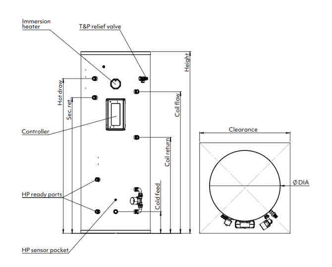
Dimensions and clearance
Warning: Position of the cylinder should suit the installation; all connections should be to the front for ease of access. The installation area must be able to cope with the cylinder, incoming pipes and discharge pipe weight when full. See the full weights table.
Note: The unit should be handled with care in order to avoid damage. It should be stored and installed upright in a dry place.
| Product Code | Height | Dia. | Hot draw |
Sec. return |
Coil flow | Coil return | Cold feed | Clear-ance |
| Direct | mm | |||||||
| 120-ELE-582 | 986 |
582 |
760 | -- |
-- |
-- |
185 |
700 |
| 150-ELE-582 | 1166 | 940 | ||||||
| 180-ELE-582 | 1346 | 1120 | ||||||
| 210-ELE-582 | 1526 | 1300 | 1140 | |||||
| 250-ELE-582 | 1766 | 1540 | 1380 | |||||
| 300-ELE-582 | 2066 | 1840 | 1680 | |||||
| Direct Slim | mm | |||||||
| 120-ELE-475 | 1250 |
475 |
1070 | -- |
-- |
-- |
185 |
550 |
| 150-ELE-475 | 1440 | 1260 | ||||||
| 180-ELE-475 | 1690 | 1510 | ||||||
| 210-ELE-475 | 2000 | 1820 | 1710 | |||||
| Indirect | mm | |||||||
| 120-IND-582 | 986 |
582 |
760 | -- | 650 | 475 |
185 |
700 |
| 150-IND-582 | 1166 | 940 | 830 | 550 | ||||
| 180-IND-582 | 1346 | 1120 | 1010 | 730 | ||||
| 210-IND-582 | 1526 | 1300 | 1140 | 1190 | 805 | |||
| 250-IND-582 | 1766 | 1540 | 1380 | 1430 | 1045 | |||
| 300-IND-582 | 2066 | 1840 | 1680 | 1730 | 1345 | |||
| Indirect Slim | mm | |||||||
| 120-IND-475 | 1250 |
475 |
1070 | -- | 960 | 740 |
185 |
550 |
| 150-IND-475 | 1440 | 1260 | 1150 | 930 | ||||
| 180-IND-475 | 1690 | 1510 | 1400 | 1180 | ||||
| 210-IND-475 | 2000 | 1820 | 1710 | 1710 | 1490 | |||
Hydraulic installation
Unvented installations
In the case of an unvented installation, install of this product should only be carried out by a competent operative (i.e. the installer must have attended a recognised course in unvented hot water systems or received appropriate training in their apprenticeship).
Installers should ensure incoming mains pressure is less than 1 MPa (10 bar) and at-least 0.1 MPa (1 bar) with a minimum flow rate of 10 L/min. Local authority approval for installation of unvented systems must be granted.
Connection guidelines
Excessive use of flux can damage the unit, especially the valves and expansion vessel. Avoid over-use and ensure the system is fully flushed of any debris and flux after connection. If a full sterilisation of all the pipework including the cylinder is required then a complete drain down and flush of the unit is essential. A simple flush through with water is not adequate in removing all sterilising solution within the cylinder. Under no circumstances should sterilising solution be left in the cylinder any longer than required.
22mm pipework is recommended to ensure adequate flow rate. The unit is supplied with a inlet control valve that has a set pressure of 0.3 MPa (3bar). The valve also consists of a serviceable strainer, non-return valve, expansion relief valve, connection for an expansion vessel and balanced cold feed supply. We would strongly recommend fitting an isolating valve prior to the inlet control valve for ease of maintenance at a later date.
Under no circumstances should an isolating valve be fitted between the expansion valve and the storage cylinder.
Drain and service
Please ensure that a drain valve is fitted to the lowest part of the unit, The drain valve must be fitted as low as possible so that at least 80% of the cylinder’s total capacity can be drained off when required.
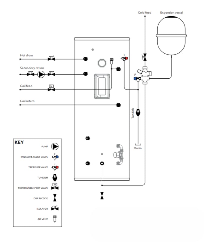
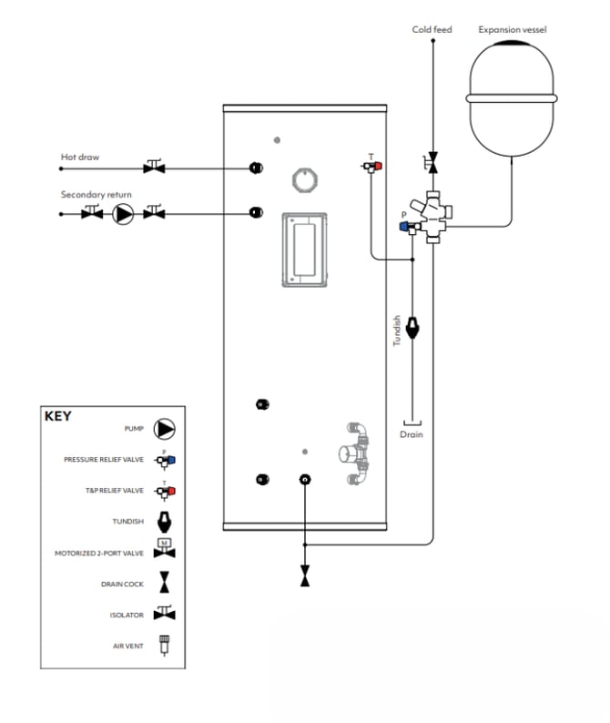
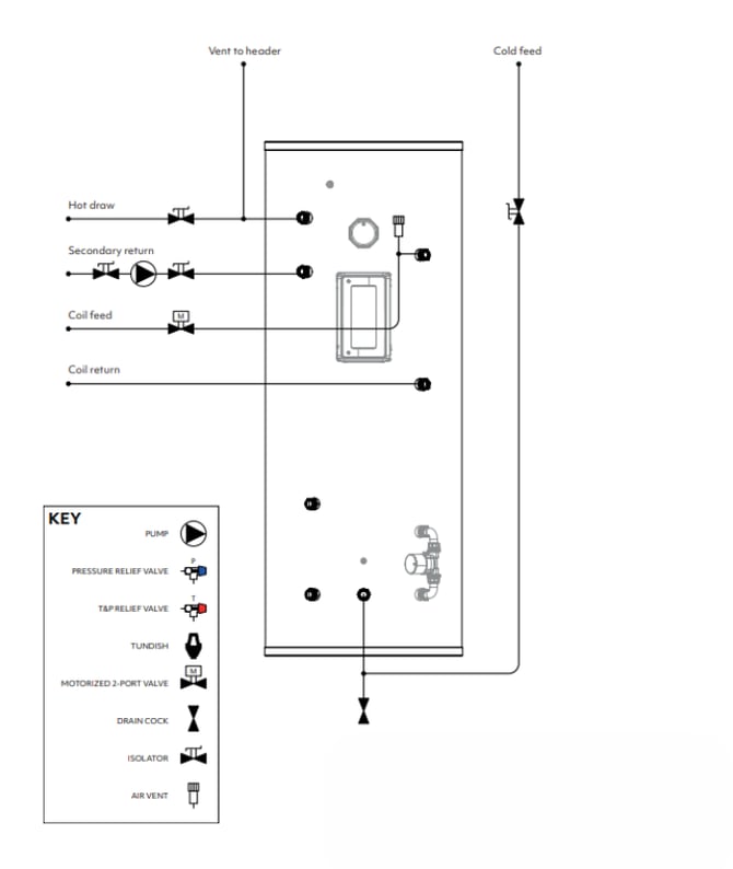
Hydraulic schematics
Indirect unvented
Note: It is recommended to insulate coil feed, return, hot draw and secondary return pipes within 2m of their cylinder connections.
Direct unvented
Note: It is recommended to insulate hot draw and secondary return pipes within 2m of their cylinder connections.
Indirect vented
Note: It is recommended to insulate coil feed, return, hot draw and secondary return pipes within 2m of their cylinder connections.
Direct vented
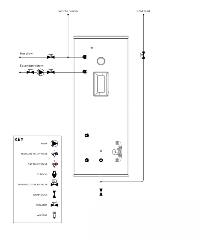
Note: It is recommended to insulate coil feed, return, hot draw and secondary return pipes within 2m of their cylinder connections.
Discharge pipework
| Sizing of discharge pipes D1 and D2 | ||||
|
Valve outlet size |
Min. Diameter D1 |
Min. Diameter D2 | Maximum D2 pipe length | Equivalent length added by each elbow / bend |
| mm | mm | m | m | |
|
G 1/2” |
15 |
22 | < 9 | 0.8 |
| 28 | < 18 | 1.0 | ||
| 35 | < 27 | 1.4 | ||
|
G 3/4” |
22 |
28 | < 9 | 1.0 |
| 35 | < 18 | 1.4 | ||
| 42 | <27 | 1.7 | ||
Discharge pipes from safety devices
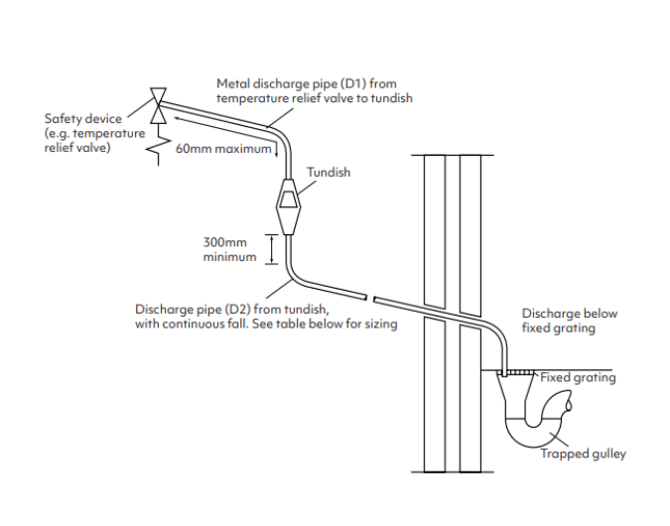
- Safety devices such as temperature relief valves or combined temperature and pressure relief valves should discharge either directly or by way of a manifold via a short length of metal pipe (D1) to a tundish.
- The diameter of discharge pipe (D1) should be not less than the nominal outlet size of the safety device, e.g. temperature relief valve.
- Where a manifold is used it should be sized to accept and discharge the total discharge from the discharge pipes connected to it.
- Where valves other than a temperature and pressure relief valve from a single unvented hot water system discharge by way of the same manifold that is used by the safety devices, the manifold should be factory fitted as part of the hot water storage system unit or package.
Tundish
The tundish, which shows visible discharge from the relief valves, is to be in a prominent, visible and safe position away from any electrical devices.
The tundish should be vertical, located in the same space as the unvented hot water storage system and be fitted as close as possible to, and lower than, the safety device, with no more than 600mm of pipe between the valve outlet and the tundish.
Discharge pipe D2
The discharge pipe (D2) from the tundish should have a vertical section of pipe at least 300mm long below the tundish before any elbows or bends in the pipework. It should be installed with a continuous fall of at least 1 in 200.
The discharge pipe (D2) should be made of metal or other material that has been demonstrated to be capable of safely withstanding temperatures of the water discharged and is clearly and permanently marked to identify the product and performance standard (e.g. as specified in the relevant part of BS 7291-1:2006.)
The discharge pipe (D2) should be at least one pipe size larger than the nominal outlet size of the safety device unless its total equivalent hydraulic resistance exceeds that of a straight pipe 9m long, i.e. for discharge pipes between 9m and 18m the equivalent resistance length should be at least two sizes larger than the nominal outlet size of the safety device; between 18 and 27m at least 3 sizes larger, and so on; bends must be taken into account in calculating the flow resistance.
Where a single common discharge pipe serves more than one system, it should be at least one pipe size larger than the largest individual discharge pipe (D2) to be connected.
Note: An alternative approach for sizing discharge pipes would be to follow Annex D, section D.2 of BS 6700:2006 + A1:2009 Specification for design, installation, testing and maintenance of services supplying water for domestic use within buildings and their curtilages.
The discharge pipe should not be connected to a soil discharge stack unless it can be demonstrated that the soil discharge stack is capable of safely withstanding the temperatures of the water discharged, in which case, it should contain a mechanical seal, not incorporating a water trap, which allows water into the branch pipe without allowing foul air from the drain to be ventilated through the tundish.
If plastic pipes are used as branch pipes carrying discharge from a safety device, they should be either polybutylene (PB) or cross-linked polyethylene (PE-X) complying with national standards such as Class S of BS 7291-2:2006 or Class S of BS 7291-3:2000 respectively; and be continuously marked with a warning that no sanitary appliances should be connected to the pipe.
Where pipes cannot be connected to the stack it may be possible to route a dedicated pipe alongside or in close proximity to the discharge stack.
Termination of discharge pipe
The discharge pipe (D2) from the tundish should terminate in a safe place where there is no risk to persons in the vicinity of the discharge.
Examples of acceptable discharge arrangements are:
- To a trapped gully with the end of the pipe below a fixed grating and above the water seal.
- Downward discharges at low level; i.e. up to 100mm above external surfaces such as car parks, hard standings, grassed areas etc. are acceptable providing that a wire cage or similar guard is positioned to prevent contact, whilst maintaining visibility.
- Discharges at high level: e.g. into a metal hopper and metal downpipe with the end of the discharge pipe clearly visible or onto a roof capable of withstanding high temperature discharges of water and 3m from any plastic guttering system that would collect such discharges.
Electrical installation
Warning: Ensure all electrical supplies are switched off before making any connection to the unit.
Electrical installation must be carried out by a competent electrician and be in accordance with the latest I.E.T. regulations.
External wiring
Mixergy cylinders come supplied with cable included. Any extensions to the supplied cabling must be sized to latest I.E.T regulations.
Primary supply (13A, 230-240V~, 1.5mm2 CSA)
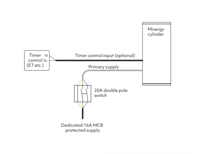
White 3-core (L,N,P.E) cable labelled ‘PRIMARY SUPPLY’. Used for the primary electrical supply of the appliance including the pre-fitted immersion heater.
Timer control (VOLT-FREE, 10mA 80-240V~, 0.5mm2 CSA)
Black 3-core (L,N,P.E) volt free cable labelled ‘TIMER CONTROL’ . Used to allow a third party controller or timer to instruct the cylinder to heat via a switched live signal.
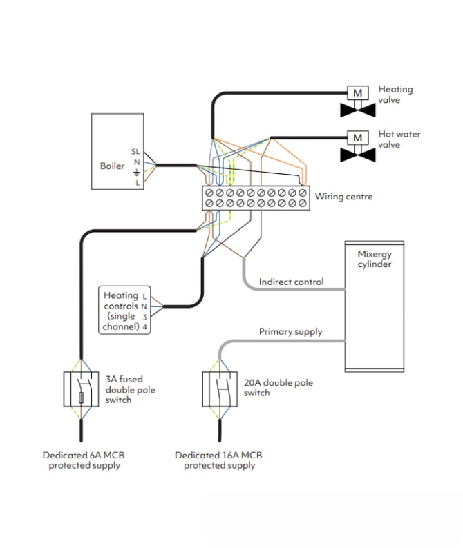
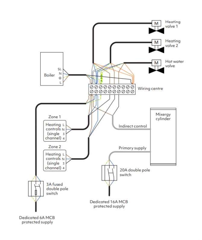
Indirect control (VOLT-FREE, 6A 240V~ MAX, 0.75mm2 CSA)
White 4-core (BLACK(C), BROWN(1), GREY(2), GREEN/YELLOW(P.E)) volt free cable labelled ‘INDIRECT CONTROL’. Used for switched (on/off) control of an indirect heat source. When the cylinder calls for heat, the voltage supply on C will be switched from 2(GREY) to 1(BROWN).
Note: Both the timer control cable and indirect control cable are attached to volt free contacts within the controller and can be safely left tucked away if not required.
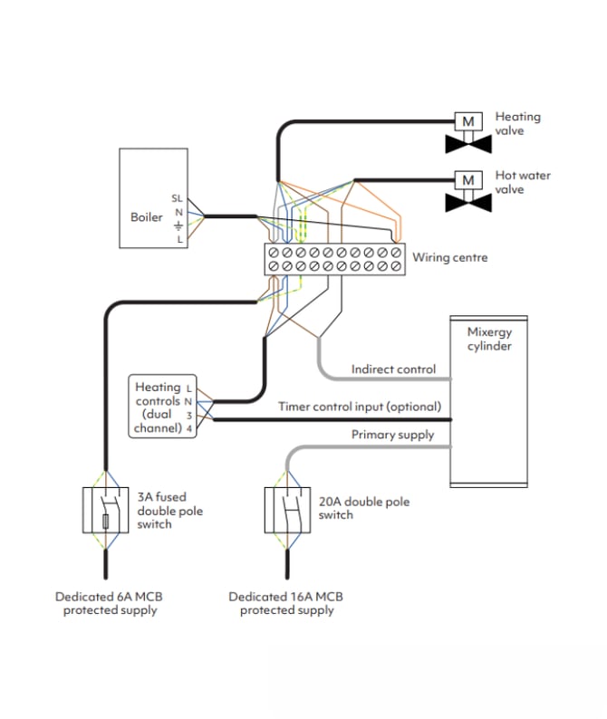
Wiring diagrams
Direct electric
 S plan (single channel heating controller)
 S plan 2-zone (single channel heating controller)
 S plan (dual channel heating & hot water controller)
Commissioning
Warning: All pre-fitted valves and fittings must be checked for tightness prior to filling. It is the installer’s responsibility to ensure that the system is water tight once installed.
Fill and pressurize
Open the hot tap furthest from the cylinder. Open the cold water inlet isolator to the cylinder. Close the hot tap once water flow is observed through the furthest tap. Open all other hot water taps in turn to purge air from the pipes. Finally, close all the hot water taps to pressurize the system.
Check the system for leaks - it is strongly recommended to have one installer next to the cylinder during the pressurization process to catch any leaks as they occur.
Check that the safety valves are operating correctly, turn the tops of the valves independently to ensure water passes through the valve and into the tundish. Once this is confirmed, open both valves together allowing as much water as possible to flow through the tundish. Make sure that your discharge pipework is free from debris and is transporting the water away to waste effectively. The valves can then be released and a check should be made to ensure they have re-seated correctly.
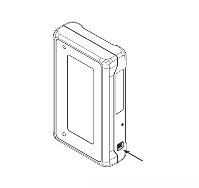
Connect the gauge
Plug the gauge into the port on the right hand side of the cylinder controller.
 Connect to the internet
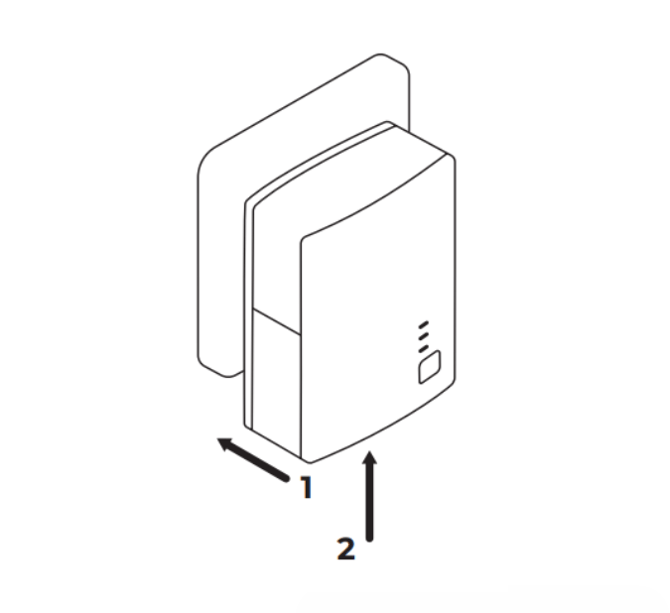
Installing the powerline adapter
The Mixergy cylinder requires internet connectivity to allow for full control of the system. Connection to the cylinder can be made using the provided ethernet to powerline adapter or by hard-wired ethernet.
Note: If an existing HomePlug AV powerline network is installed at the property, it is recommended to pair the cylinder with the existing network as detailed in the troubleshooting section. Powerline connectivity between the cylinder and internet router is only possible in houses where both the cylinder and adapter are powered from the same electrical phase.
- Plug the powerline adapter into a wall socket within 2m of the internet router.
- Plug the powerline adapter into the internet router using the included 2m
ethernet cable.
 Wiring an ethernet connection
Warning: Ensure all electrical supplies are switched off before opening the cylinder controller cover.
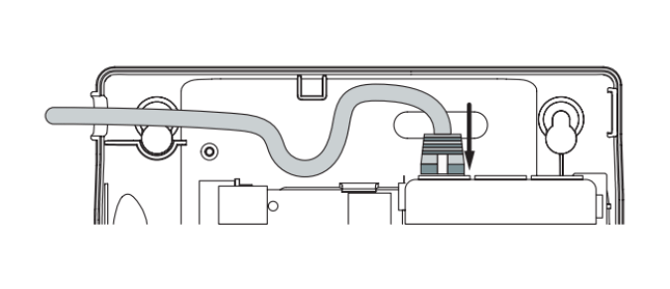
If a hard-wired CAT5/CAT5e/CAT6 network connection is desired, this can
be achieved as follows:
1. Unscrew and remove the cylinder controller’s cover and then disconnect
the blue ethernet cable as shown.
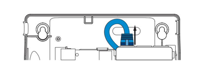 2. Replace the removed ethernet cable with a suitable direct connection to
the network (broadband router/switch).
 Check start-up self-test
During boot, the controller will run a self diagnostic test. Results for this test are shown on the gauge as per the diagram below. Refer to the troubleshooting section if your self test result is not as shown below.
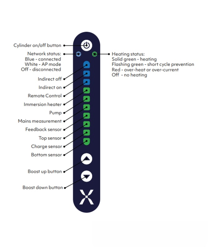 Self-test troubleshooting
Sensor
If any of the 4 sensor results (bottom, charge, top and feedback) show a red LED, double check that the ‘CYL SENSOR’ is correctly plugged in and the cylinder is within a safe temperature range (between 5 °C and 65 °C.) Try unplugging and plugging the sensor. If the problem persists, please see Installer Support.
Mains measurement
Double check the incoming supply connection. If the fault persists, please contact Mixergy via. the support hub.
Pump
Check that the cylinder’s circulator pump cable is plugged into the ‘PUMP 1’ header. Check the pump is correctly plugged into the pump cable extension. If the problem persists, please contact Mixergy via. the support hub.
Immersion heater
Check that the cylinder’s immersion heater is plugged into the ‘HEATER 1’ header. Check that the immersion thermostat is set to the maximum value. Ensure the cylinder is not over-heated (>65 °C.) If a PV diverter is fitted, ensure it is plugged into the zoneBUS network of the controller. If the diverter has not been factory fitted, ‘device discovery’ may need to be run via the app in order to configure the PV diverter. If the problem persists, please contact Mixergy via. the support hub.
Remote control, Indirect on/off
Check that a blue LED is shown. If a remote control signal is present, the remote control LED should light green. If any other colour is shown, please contact Mixergy via. the support hub.
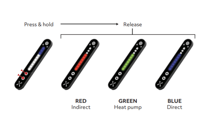
Heat source setting
For offline controllers, heat source can be set using the cylinder’s gauge by first putting the gauge into ‘heat source selection mode’. This is done by pressing and holding the boost up and boost down buttons simultaneously until the display fills white and begins to cycle between the heating modes as shown below. Release the buttons when the correct heating mode is shown on the display.
 Scheduling
For offline controllers with third party scheduling via the timer control cable, scheduling should be set on the third party control and correct operation of the schedule should be verified by the installer. For installations using the Mixergy controller for scheduling, setup should be performed on the Mixergy app. Refer to the quick start guide.
Commissioning Checklist
The Commissioning Checklist is to be completed by the competent person who commissioned the storage system as a means of demonstrating compliance with the appropriate Building Regulations and then handed to the customer to keep for future reference. This can be found in the physical booklet.
Failure to install and commission this equipment to the manufacturer’s instructions may invalidate the warranty but does not affect statutory rights.
Troubleshooting
Attention: Discharge from either of the relief valves indicates a malfunction in the system and must be investigated immediately.
Overheated water
In the unlikely event of overheated (95°C) water being discharged, the Mixergy controller should be switched off immediately and a competent engineer called out. Please contact Mixergy see Installer Support. Do not shut off the cold water supply to the unit.
Cross flow
If all the valves have been replaced and the vessel re-commissioned then the system could be suffering from cross flow, this is when the hot and cold systems are not balanced and higher pressure cold water is forced back into the cylinder. If this is the case then an additional pressure reducing valve may be required to reduce the cold water supply pressure.
Immersion heaters
If the immersion heater is not heating the water adequately it has either failed (in which case a replacement immersion heater as supplied by Mixergy should be fitted), an electrical fault is present or the electrical cutout has operated due to the control thermostat being set too low or being faulty. Activate the reset button under the immersion cover. If the problem persists please see our Installer Support.
Safety valves
If all previous checks have been done and water is still being discharged from either safety valve, determined which valve is faulty and replace with one supplied by Mixergy.
Draining the Cylinder
- Switch off the immersion heater(s), boiler and any other heat sources.
- Switch off water at mains.
- Open nearest hot tap.
- Open drain to start draining the cylinder.
To re-fill follow the commissioning instructions.
Flushing the cylinder
To flush out the system, drain the unit as above, fill and repeat. If after recharging the expansion vessel the cylinder is still discharging, it may be due to cross-flow - ensure appropriate check valves are fitted. The pressure reducing valve, one of the relief valves, or the expansion vessel may have failed. The component should be identified and replaced by one supplied by Mixergy.
Service Instructions
ANNUAL MAINTENANCE should be performed by a competent operative. If this system is not protected under an active Mixergy Care subscription, failure to maintain this system in accordance with these instructions will invalidate the manufacturer’s warranty. A maintenance record should be kept in the service record of this booklet.
We recommend either a Mixergy care subscription or a third party service program is arranged on installation.
Annual service checks
- Expansion relief valve– manually open the twist cap and check that the water is discharged and runs clearly through the Tundish and out at the final discharge point. Ensure that the valve re-seats/re-seals itself.
- Pressure & temperature relief valve - repeat the above procedure. Ensure that the valve re-seats/re-seals itself.
- Strainer - turn off mains at stopcock or isolate the inlet control valve. De-pressurize the system by opening a hot water tap or relief valve. There will be a small amount of residual water in the pipework, remove the cartridge from Pressure Reducing Valve, clean Strainer and replace.
- Expansion vessel - check pressure via the Schrader valve on top of the vessel, located under the plastic cap. Ensure pressure reads 30 MPa (3 Bar) when the cylinder is de-pressurized. Vessel can be recharged if required using a compatible tyre pump.
- Water pressure - check the water pressure of the system is no more than
35 MPa (3.5 bar) during operation.
Unlinking an account
To unlink a controller from an existing Mixergy account, press and hold the boost down and power buttons on the gauge simultaneously for 15 seconds. If the controller has no gauge attached, please see Installer Support to unlink the existing account.
Replacement parts
Do not attempt to repair or replace any parts of this product unless you are a trained operative. If you suspect a fault or a replacement part is needed, please visit Installer Support.
| Part description | Part number |
| Controller assembly | MAS0068 |
| Pump assembly | MAS0093 |
| Pump cable | MAS0083 |
| Immersion cable (standard) | MAS0215 |
| Immersion heater | MEL0022 |
| Immersion thermostat | MEL0018 |
| 2-port valve | MEL0023 |
| Tundish | MME0292 |
| Inlet control valve | MME0291 |
| T&P relief valve | MME0095 |
| Expansion vessel | MME0290 |
| Gauge | MAS0198 |
Disposal
In accordance with European Directive 2012/19/EU and the Waste Electric and Electronic Equipment (WEEE) Regulations 2013 on waste electrical and electronic equipment, used electrical devices must be collected separately and recycled in an environmentally responsible manner.
Used devices should be returned to your dealer or a local, authorised collection and disposal system. Failure to comply with this EU Directive may result in a negative impact on the environment.
Previous versions
- MDC0001-17 (PDF 2.2MB)
- MDC0001-16 (PDF 2.2MB)
